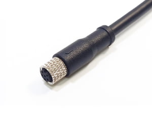
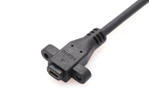
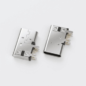
If you’re sourcing a connector (for a broader overview, see What Is a Connector? A Practical Overview for OEM Buyers) from a part number on a drawing and you think matching the pin count and dimensions is enough — this article covers what dimensions don’t tell you and what determines whether the connector will actually work in your assembly.
Direct answer: USB Type-A, USB Type-B, USB Type-C, USB Mini-B, and USB Micro-B are the most common mechanical interface families named on drawings and BOMs. USB Type-A is the flat rectangular host-side port; USB Type-B is the square or beveled device-side connector; USB Type-C is the reversible 24-pin interface that may carry USB 2.0, USB 3.2, or USB Power Delivery depending on implementation; USB Mini-B and Micro-B are smaller legacy device-side connectors. The name identifies the mating interface family — not termination style, plating stack, retention method, or process compatibility.
Engineering Decision Matrix: USB Form Factor vs. Target Environment
| Form Factor | Pins | Max Data / Spec | Current / Voltage Rating | Typical Mating Cycles | Primary Physical Failure Mode | Recommended PCB Anchor |
|---|---|---|---|---|---|---|
| Type-A | 4 (USB 2.0) / 9 (USB 3.2) | 480 Mbps / 10 Gbps | 1.5A @ 5V (up to 4.5W) | 1,500 (Std) / 5,000 (High-durability) | Shell spring-finger fatigue, solder-joint shear | Through-hole solder stakes with board lock |
| Type-B | 4 (USB 2.0) / 9 (USB 3.2) | 480 Mbps / 5 Gbps | 1.5A @ 5V | 5,000 | Contact tongue cracking under heavy torque | Dual through-hole grounding tabs |
| Type-C | 12 to 24 | 480 Mbps to 40 Gbps (USB4) | Up to 5A @ 48V (240W EPR) | 10,000 | Mid-plate delamination, tongue fracture, solder bridge | Hybrid (SMT signal leads + Through-hole shell pegs) |
| Mini-B | 5 | 480 Mbps | 1.0A @ 5V | 5,000 | Port clearance expansion, cold solder joints | Through-hole hold-down tabs |
| Micro-B | 5 (USB 2.0) / 10 (USB 3.0) | 480 Mbps / 5 Gbps | 1.8A (BC 1.2) / 0.9A @ 5V | 10,000 (USB 2.0) / 1,500 (USB 3.0) | Latch tab flattening, contact pin stubbing | Surface-mount tabs with center solder anchor |
USB Connector Families: What the Drawing Name Actually Means
USB Type-A, USB Type-B, USB Type-C, USB Mini-B, and USB Micro-B are interface families defined by the USB-IF, not brand-specific product names. A BOM line often pairs the generic family with a manufacturer series number that controls exact dimensions, materials, and process. That series number is the engineering document that matters for production.
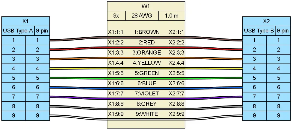
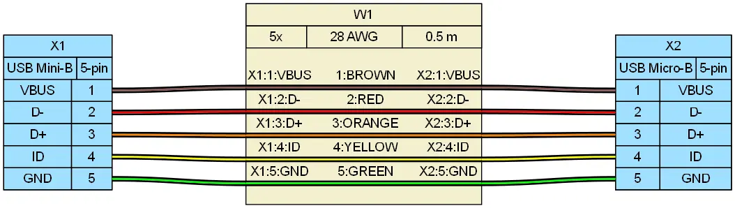
USB Type-A is the flat rectangular host-side port used in PCs, hubs, industrial panels, and test equipment. USB 2.0 and USB 3.2 Type-A versions differ in internal contact rows and key details even when the outer shell looks similar. USB Type-B is the square or beveled device-side connector common on printers, benchtop instruments, and industrial equipment; USB 3.2 Type-B adds a top block and is physically incompatible with USB 2.0 Type-B. USB Type-C(covered in our What Is a USB-C Connector? A Practical FAQ for OEM Buyers) is a 24-pin reversible mechanical interface. The same shape can support USB 2.0 only, USB 3.2, or USB Power Delivery, so the connector name alone does not define electrical capability. USB Mini-B (5-pin) and USB Micro-B (5-pin for USB 2.0; 10-pin dual-cavity for USB 3.0/3.2 Gen 1) serve legacy and industrial peripherals. While Mini-B features a thicker trapezoidal shell favored for mechanical robustness in legacy test rigs, USB 3.0 Micro-B expands width by adding a separate 5-pin high-speed differential block alongside the standard micro shell, introducing distinct tooling retention and side-loading vulnerability under EIA-364-38 cable pull conditions.
| Connector Family | Typical Mating Interface | USB Version Variants | What the Family Name Does Not Specify |
|---|---|---|---|
| USB Type-A | Flat rectangular host-side port | USB 2.0, USB 3.2 | Through-hole vs. SMT tail, plating stack, board lock style |
| USB Type-B | Square or beveled device-side | USB 2.0, USB 3.2 | USB 3.2 top block compatibility, tail geometry, anchor type |
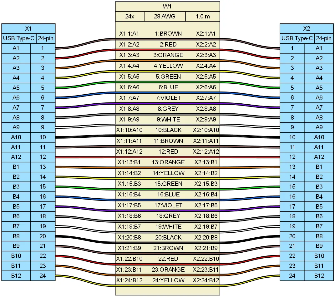
| USB Type-C | Reversible 24-pin | USB 2.0, USB 3.2, USB Power Delivery | Mid-plate thickness, tongue position, supported data rate, SMT pattern |
| USB Mini-B | Smaller legacy device-side | USB 2.0 | Strain relief design, shell plating, wire gauge range |
| USB Micro-B | Small legacy device-side | USB 2.0, USB 3.0 | USB 3.0 width increase, terminal style, spring tab retention |
The Gap Between a Connector Name and a Production-Ready Part
A drawing or BOM often provides only the connector name and a manufacturer part number. It rarely states termination style, plating stack, retention hardware, or process window. For cable-side connectors, wire gauge range and insulation diameter are not visible from the outer shell. For PCB-mount connectors, footprint and tail geometry determine whether the part can be soldered with the existing reflow or wave profile.
USB connector families may share the same mating interface but differ in tail style: through-hole, surface-mount, hybrid, mid-mount, top-mount, or cable-to-panel variants. A USB Type-A receptacle can be a through-hole part on one drawing and an SMT part on the next, with completely different board preparation requirements.
We regularly see connectors that pass visual incoming inspection but fail during assembly — the termination interface or plating stack was engineered for a different process than the one running on the production line. The part looks right; the process doesn’t know it’s wrong.
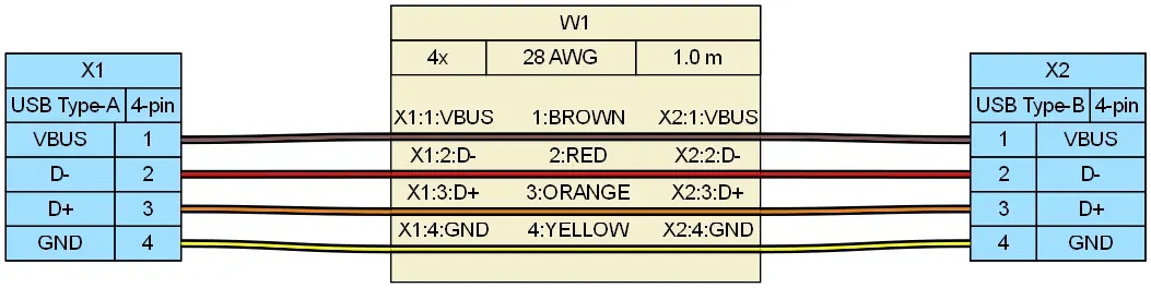
For USB cable assemblies, a supplier reviewing the actual wire construction — not just the connector shell — can confirm whether the chosen AWG fits the crimp terminal range. This is a core input in custom cable assembly projects.
Termination Compatibility: Where Pin Count and Outer Shape Fail
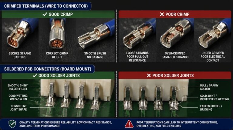
Crimp-type and solder-type USB cable connectors require strict wire gauge and insulation outer diameter (OD) matching. Squeezing an AWG 24 power lead into a crimp barrel dimensioned for AWG 28 breaches IPC/WHMA-A-620 Class 3 terminal acceptance criteria, causing split crimp wings, improper conductor extrusion, and failed tensile pull-force ratings. Conversely, pairing undersized wire with an oversized insulation barrel destroys mechanical strain relief, concentrating bending fatigue directly on the conductor strands during flexural endurance cycles.
PCB-mount USB connectors require soldering process compatibility. A USB Type-C SMT receptacle needs a reflow window and solder paste stencil matched to the shell leads. A through-hole USB Type-A stack may need wave soldering or selective soldering. The same mating face does not mean the same PCB process.
USB 3.2 connectors add high-speed differential pairs, ground shielding, and tighter pad alignment requirements, making termination quality more critical than in USB 2.0-only designs. Before treating a connector as a drop-in replacement, compare tail geometry, lead coplanarity, standoff height, and the manufacturer’s recommended PCB pad layout — not just the mating face.
Plating and Mechanical Retention: Invisible Parameters That Decide Reliability
Contact plating material and thickness govern mating-cycle life, corrosion resistance, and solderability. A thin gold flash on a USB Type-A contact is not equivalent to heavier gold plating over nickel for repeated insertion or humid environments. The same applies to USB Type-B and USB Micro-B contacts.
A USB connector may look identical but use different shell plating, which affects solder wetting and salt-spray performance in industrial equipment. RoHS-compliant options require plating and materials that do not exceed restricted substance thresholds under the RoHS[1] directive.
Mechanical retention varies widely. USB Type-C receptacles rely on latch geometry and mid-plate thickness. USB Micro-B depends on spring tabs. Board-mount USB Type-A and Type-B may use through-hole anchors, board locks, or SMT pegs. If the replacement part has the same mating face but weaker shell stakes or a thinner mid-plate, it may seat loosely or fail after only a few hundred cycles.
Compatible vs. Interchangeable: A Comparison That Changes Sourcing Decisions
“Compatible” often means the plug fits the socket and the pin count matches. “Interchangeable” means the part can be substituted without changing the PCB footprint, wire gauge range, process, or retention. In USB sourcing, the distinction drives whether a second source is a minor paperwork change or a board redesign.
USB Type-A through-hole and SMT versions share the same mating face but require different board preparation. They cannot be interchanged on the same PCB without layout changes. USB 2.0 Micro-B and USB 3.0 Micro-B look related, but USB 3.0 Micro-B is physically wider and adds pins. A cable assembly built for one will not fit the other.
Two USB Type-C receptacles with the same 24-pin count may differ in mid-plate thickness, tongue position, and SMT tail pattern. One may be rated for USB 2.0 only while the other supports USB 3.2 and USB Power Delivery. Pin count alone does not make them interchangeable.
USB Connector Verification Checklist Before Ordering
Use the following checklist before committing a USB connector to production. Each line separates a visual or dimensional check from a process-level verification.
| Verification Step | Specific Checks | Why It Matters |
|---|---|---|
| Termination method | Crimp/cable side or through-hole/SMT/hybrid; wire gauge range or PCB footprint | A visually matching part may not fit the actual production line |
| Plating specification | Gold thickness, nickel underplate, shell finish, RoHS status | Plating controls mating cycles, corrosion resistance, and solderability |
| Key dimensions | Measure mating depth, tail position, standoff, shell stakes on real samples | Datasheet drawings alone do not capture supplier process variation |
| Mating interface | Pin sequence, keying, latch type, USB generation, USB Power Delivery capability | A 24-pin Type-C shell can support very different electrical specs |
| Series number | Request full manufacturer datasheet; compare drawings revision to revision | Manufacturer series controls tolerances not visible in a BOM line |
If a USB connector on your drawing or BOM needs a second source or a build-to-print cable assembly, submit the part number and target process for a connector matching review before sampling.
What to Submit for a USB Connector Matching Review
Provide the drawing, BOM line, target application, and assembly process. Include a sample or photo if available. Specify termination type, wire gauge or cable construction, environmental conditions, required mating cycles, and any USB 2.0, USB 3.2, or USB Power Delivery requirement.
Ask for a sample before committing to production. Inspect for termination compatibility, plating, retention, and mating feel — not just visual appearance. For OEM wire harness builds that embed USB connectors, share routing and strain-relief requirements within the wire harness manufacturing process. Plan for incoming quality inspection and export packaging checks before production release.
To prevent line-down incidents, EDOM Electronics executes a structured Design-for-Manufacturability (DFM) verification for custom USB assemblies within 24 hours. Our engineering team audits your 2D/3D models against reflow profile windows, tail coplanarity (<0.08 mm), shell stake retention, and wire-to-terminal crimp pull ratings. We provide 3–5 day rapid first-article prototyping and terminal micro-section analysis to validate impedance continuity and weld integrity before opening hard tooling. For project review, submit your assembly drawings or explore our electronic connector sourcing options.
Frequently Asked Questions
What is the difference between USB Type-A and USB Type-C?
USB Type-A has a flat rectangular shape with a non-reversible insertion orientation and is typically host-side. USB Type-C uses a reversible 24-pin interface that can carry USB 2.0, USB 3.2, or USB Power Delivery depending on implementation. The two are physically incompatible without an adapter.
Can I replace a USB 2.0 Type-A connector with a USB 3.2 Type-A part if the outer dimensions match?
Not automatically. USB 3.2 Type-A connectors add internal contact rows and may require a different PCB footprint, tail geometry, and high-speed signal routing. Confirm the manufacturer’s recommended pad layout and terminal style before substituting.
How do I know if a USB connector is compatible with my PCB soldering process?
Check the tail type: through-hole parts typically require wave or selective soldering, while SMT parts require a reflow profile and solder paste stencil matched to the shell leads. Verify lead coplanarity, standoff height, and the recommended PCB pad layout on production samples.
Does USB Type-C always support USB Power Delivery?
No. USB Type-C defines the mechanical interface, but USB Power Delivery is a separate protocol and power negotiation layer. A USB Type-C receptacle can be USB 2.0-only, USB 3.2-only, or support specific USB Power Delivery voltage and current ratings. Check the manufacturer’s electrical specification, not just the shell.
What should I include in a USB connector RFQ for matching?
Include the drawing, BOM line, target application, assembly process, termination method, wire gauge or PCB footprint, plating requirements, environmental conditions, required mating cycles, and the intended USB data or power standard. A physical sample or clear photo improves matching accuracy.
Key Takeaways
- USB Type-A, Type-B, Type-C, Mini-B, and Micro-B are mating interface families — not complete production specifications.
- Pin count and outer shape do not confirm termination compatibility, plating stack, or mechanical retention.
- Verify wire gauge range for cable-side connectors and PCB footprint plus soldering profile for board-mount connectors.
- Ask for real samples and inspect termination, plating, retention, and mating feel before production release.
- “Compatible” is not the same as “interchangeable” — the distinction often determines whether a board or cable design must change.