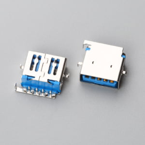
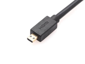
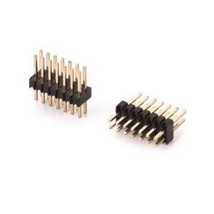
If you’re sourcing a connector from a part number on a drawing and you think matching the pin count and dimensions is enough — this article covers what dimensions don’t tell you and what determines whether the connector will actually work in your assembly.
A CAN bus connector(see our CAN Bus Connector FAQ: Practical Answers for OEM Buyers and Design Engineers) is a physical interface that carries the two-wire differential Controller Area Network signals—CAN_H and CAN_L—with termination, shielding, and mechanical retention options defined by ISO 11898[1] or higher-layer standards such as J1939, used for robust data communication in automotive, heavy-duty vehicle, and industrial control systems.
What the Connector Name on a Drawing or BOM Actually Tells You
A part number or drawing label can encode a brand, a product series, a shell size, a contact arrangement, or a generic descriptor such as “CAN connector.” It rarely contains all the information procurement needs to place a production order. The same label may point to a familiar form factor such as DB9 or OBD-II, but that visible shape does not reveal the termination method, plating stack, retention feature, or the specific mating interface.
Generic terms like “CAN bus connector” or “CAN interface connector” often describe a mechanical appearance, not an electrical or process specification. Brand-specific series names carry additional assumptions: the terminal series, cavity arrangement, crimp tooling, and housing material are usually defined by the manufacturer’s internal design rules. Two connectors can look nearly identical in a photograph and still require completely different tooling or soldering profiles.
When a BOM lists only a manufacturer part number, treat it as a starting point for specification recovery — not as a complete compatibility statement. The part number tells you which component was designed in; it does not tell you whether the component will work with your current assembly process, wire gauges, or panel hardware.
CAN Bus Connector Types You Will See in Real Drawings and Manuals
In real project documents, CAN connectors appear in several distinct families. Each family has its own pinout conventions, mechanical sealing requirements, and assembly constraints.
| Connector Family | Typical Form Factor | Common CAN Pinout | Typical Application | Key Verification Points |
|---|---|---|---|---|
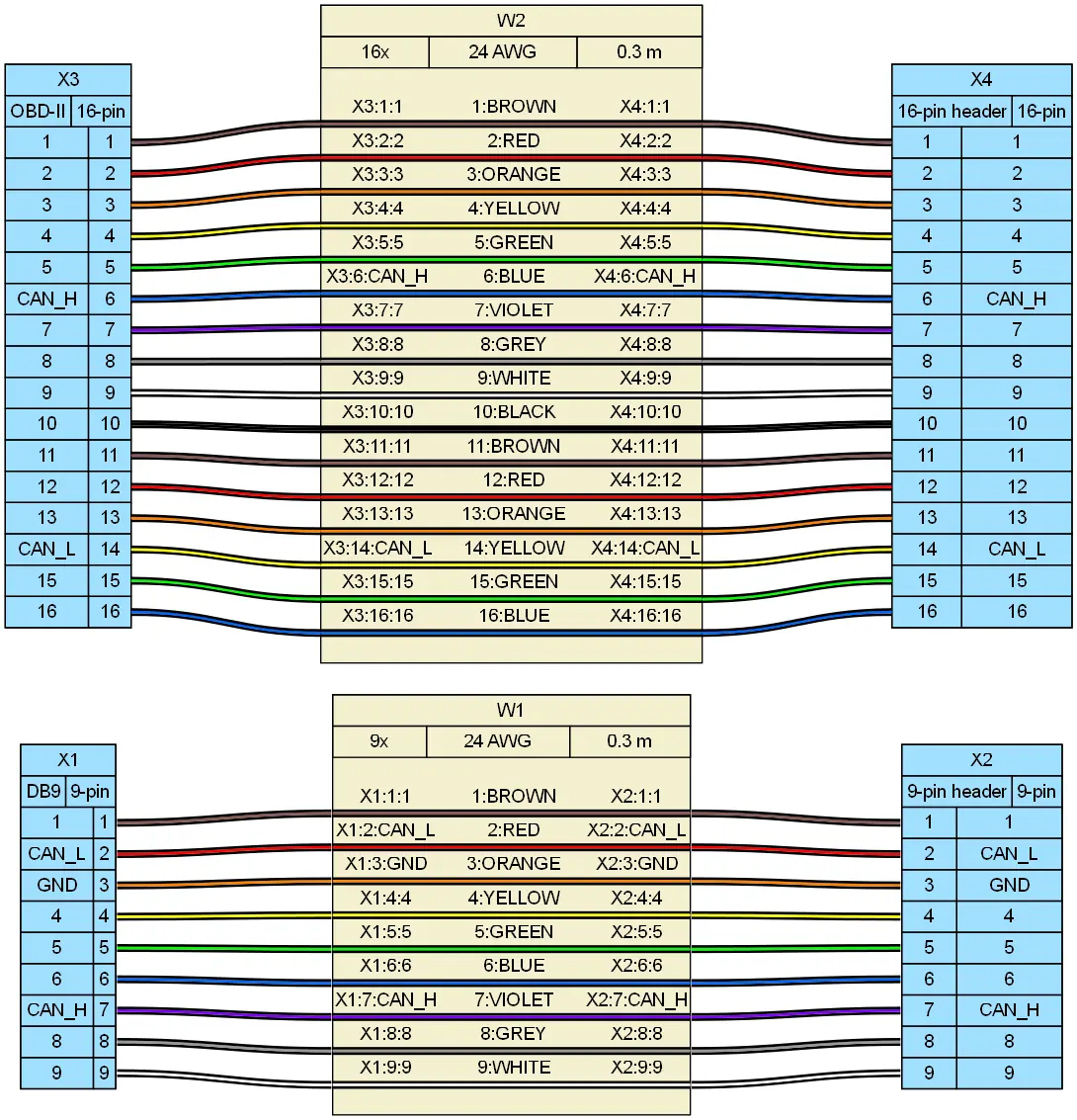
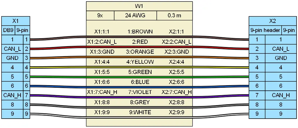
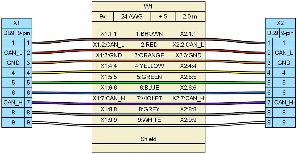
| DB9 | D-subminiature, 9-pin | Pin 2 = CAN_L, Pin 7 = CAN_H, Pin 3 = ground reference | CANopen, PC-based CAN interfaces, test equipment | Pin assignment is not universal across devices; always check the device datasheet. |
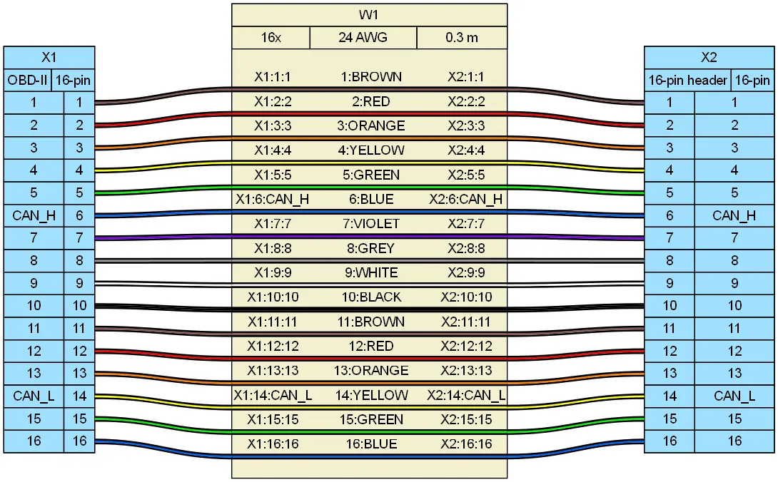
| OBD-II | 16-pin automotive diagnostic socket | Pin 6 = CAN_H, Pin 14 = CAN_L | Passenger vehicle diagnostics, fleet interfaces | Manufacturer-specific pins may differ; verify the vehicle platform. |
| J1939 / Deutsch-style | Sealed circular connector, often Deutsch DT or HD10 series | Pin assignment varies by harness and ECU function | Heavy-duty trucks, buses, off-highway equipment | Confirm sealing rating, backshell strain relief, and terminal series. |
| M12 circular | IEC 61076-compliant circular industrial connector | Typically 4- or 5-pin A-coded, with CAN_H and CAN_L on defined pin pairs | Industrial automation, robotics, IP67-rated machinery | Check coding, gender, and whether the connector is field-wireable or overmolded. |
| Terminal block / open style | Screw, spring-clamp, or pluggable terminal | Labeled CAN_H and CAN_L positions on the PCB or housing | Control cabinets, prototyping, low-vibration industrial nodes | Confirm wire gauge range and whether the terminal accepts ferrules or solid wire only. |
DB9 connectors appear frequently in CANopen and PC-based CAN interfaces. The classic CAN pinout uses pin 2 for CAN_L and pin 7 for CAN_H, with pin 3 as the ground reference. However, not every device follows the same assignment, and a DB9 shell can be terminated with solder cups, PCB pins, or IDC contacts(see our What Is an Insulation Piercing Connector? A Practical FAQ). The shell alone tells the buyer nothing about how the cable is attached.
OBD-II connectors are the 16-pin automotive diagnostic interface. For CAN, pins 6 and 14 typically carry CAN_H and CAN_L. Vehicle manufacturers may assign additional pins to body or chassis CAN networks, so the OBD-II connector on one vehicle platform is not a universal signal map for another.
J1939 applications in heavy-duty vehicles commonly use rugged circular connectors such as Deutsch DT or HD10 series. These connectors are designed for sealed, vibration-resistant environments, and the sealing performance is typically verified under IEC 60529 ingress-protection ratings such as IP67. Automotive connector systems in this category may also be validated to USCAR-2 performance requirements for mechanical integrity, electrical testing, and environmental endurance.
Industrial CAN networks may use open-style terminal blocks, M12 circular connectors, or D-sub variants. The mechanical form factor must match both the harness routing and the control cabinet or device housing. A field-wireable M12 connector may require different assembly procedures than an overmolded cable assembly, even when the pin count and coding appear identical in the drawing.
CAN_H, CAN_L, and the 120 Ohm Termination: What the Wiring Actually Requires
Controller Area Network is a two-wire differential bus. The signal is the voltage difference between CAN_H and CAN_L, not a single-ended voltage referenced to ground. This differential architecture is what allows CAN to tolerate common-mode noise in engine bays, chassis harnesses, and industrial drives. But that noise immunity only holds if the physical wiring preserves the differential pair geometry and impedance.
ISO 11898-2 specifies physical layer requirements for high-speed CAN up to 1 Mbps (and ISO 11898-1:2015 for CAN FD up to 5 Mbps). The differential bus requires a nominal 120 Ω characteristic impedance (Z₀ = 108–132 Ω) cable terminated at both logical extremes with 120 Ω ± 1%, 1/4 W resistors, yielding an equivalent DC bus resistance of 60 Ω. Placing termination at unshielded middle nodes creates impedance discontinuities, while untwisted stub lines exceeding 0.3 m (at 1 Mbps) induce signal reflection margins exceeding 15% of the differential voltage (V_DIFF), triggering bus-off frame errors.
The connector and cable assembly must preserve the characteristic impedance and the twisted-pair geometry. Untwisting too much at the connector backshell, using the wrong wire gauge for the terminal barrel, or adding an unplanned splice can create reflections. These problems will not show up in a simple continuity check. A connector that routes CAN_H and CAN_L correctly but treats the shield as an afterthought may pass continuity and still fail on the vehicle or machine.
For connector selection, this means pinout mapping, shield grounding, and termination placement have to be confirmed before crimping or soldering. High-quality custom cable assembly processes control untwist length at the connector backshell, maintain shield drain termination, and confirm the finished harness matches the intended bus topology.
Termination Compatibility: Crimp Barrel, Wire Gauge, and Solder Footprint
Crimp-type CAN connectors are engineered for a specific wire gauge range and insulation outside diameter. A terminal that fits the connector housing but is wrong for 0.5 mm² versus 0.35 mm² wire can pass visual incoming inspection and then fail during crimping or in service. The terminal barrel is designed to compress a given amount of copper; if the conductor is too small or too large, the crimp will not develop the required mechanical strength or electrical contact area.
PCB-mount connectors have a soldering footprint and a process window. Plated through-hole, surface-mount, and press-fit terminations are not interchangeable even if the mating face looks identical. A through-hole connector may not survive a reflow profile intended for SMT parts, and an SMT connector may not fit the hole pattern of an existing through-hole layout.
This is not a theoretical risk. We regularly see connectors that pass visual incoming inspection but fail during assembly — the termination interface or plating stack was engineered for a different process than the one running on the production line. The part looks right; the process doesn’t know it’s wrong.
Before ordering, compare the connector’s termination specification against the actual assembly process: hand soldering, wave soldering, reflow, or crimping with a specific tool and die set. In wire harness manufacturing, crimp-type termination specifications align with strip length, terminal barrel selection, and crimp height monitoring. If the drawing does not state the wire gauge range or insulation OD, request the manufacturer’s terminal specification before committing to a production run.
Plating Stack and Mechanical Retention: Reading the Fine Print
Plating is not just “gold or tin.” A gold flash over nickel over a base metal behaves differently from selective gold in the contact area. Pure tin finishes are highly vulnerable to fretting corrosion under engine or chassis vibration: micro-motion oxidizes tin wear debris into non-conductive tin oxide (SnO₂), leading to intermittent contact resistance spikes. Tin plating should be restricted to high-normal-force (>100 cN), low-mating-cycle (<20 cycles) connections. The full plating stack — specifying minimum 1.27 µm nickel underplate and selective 0.76 µm (30 µin) gold in mating areas — determines contact resistance stability, solderability, and long-term signal integrity under thermal cycling.
For CAN environments, vibration, temperature cycling, and mating cycles influence whether a thin gold flash, selective gold, or tin plating will maintain low contact resistance over the product’s life. Connector test sequences defined by EIA-364 cover electrical, mechanical, and environmental procedures for connector evaluation, but those procedures only produce meaningful results when the correct plating specification is known and matched to the application. In automotive or heavy-duty vehicle applications, connectors may also need to meet USCAR-2 performance requirements, which include mechanical and environmental endurance testing.
Mechanical retention methods — board locks, through-hole anchors, latch mechanisms, or bayonet coupling — affect whether the connector stays seated under harness strain and equipment vibration. Two connectors can have identical pin count and outer shell dimensions, but one has a different latch profile or board-lock location. That means it will not seat firmly in the existing panel cutout or PCB hole pattern. Housing flammability ratings such as UL 94 V-0 also matter when the device or component is required to meet flame resistance requirements, and must be specified for the exact housing material used in production.
Compatible vs. Interchangeable: What Changes at Assembly
“Compatible” means the connector performs the required electrical and mechanical function in the specific harness or PCB, under the specified assembly process and operating conditions. “Interchangeable” means the part can be substituted for another part number without changing tooling, footprint, terminal choices, or the mating connector. That is a much stricter claim.
A dimensional match can be electrically compatible but not interchangeable if the crimp tooling, solder profile, or panel latch is different. For procurement, never accept “compatible” from a catalog as “interchangeable” without confirming the four verification points in the next section. The distinction matters most on the assembly line, where a reseated terminal, a reflow profile change, or a panel cutout modification can turn a perceived cost saving into rework and delay.
Connector Verification Checklist Before You Order
Use the following verification checklist before treating any connector as a production-ready substitute. Each item must be confirmed against the actual assembly process and operating environment, not just the datasheet drawing.
| Checklist Item | Verification Action | Common Failure if Skipped |
|---|---|---|
| 1. Confirm termination method | Match to your assembly process: crimp, solder, press-fit, or IDC. Check wire gauge range and insulation OD for crimp; check footprint and soldering profile for PCB. | Terminal passes visual inspection but fails during crimping or soldering. |
| 2. Confirm plating specification | Request the exact plating stack, not just the color or the word “gold.” Verify against environmental and mating-cycle requirements. | Contact resistance rises after thermal cycling or vibration; solderability varies by batch. |
| 3. Verify key dimensions with actual samples | Check latch location, board-lock position, mating face depth, and panel cutout fit using physical samples. | Connector does not seat firmly or board locks do not align with PCB holes. |
| 4. Confirm the mating interface is fully identical | Verify shell keying, contact arrangement, pin count, gender, and sealing features against the original part. | Mating connector does not engage or sealing is compromised in the field. |
If you are sourcing from a drawing or BOM and the termination or plating data is missing, request a specification review against your assembly process before committing to a production order. A physical sample alone is not enough — sample confirmation should include termination compatibility, plating verification, and mating interface checks, not just dimensional measurement.
From Verification to Stable Supply: What to Do Next
Once the connector passes the checklist, the next risk is supply consistency. The same part number from a different production batch or an alternate source may drift in terminal plating, housing material, or board-lock geometry. These changes are often invisible in a photo and only appear when the line rejects a batch or the field returns a failure.
For OEM buyers and design teams balancing BOM targets against reliability, working with an engineering-led manufacturing partner eliminates assembly mismatch risks before production tooling is cut. EDOM Electronics provides DFM (Design for Manufacturability) audits on connector cross-references, crimp cross-section analysis to IPC/WHMA-A-620 Class 3, and 3–5 day rapid functional prototyping for custom CAN cable assemblies. Reviewing terminal extraction forces, backshell IP67 sealing options, and NRE mold optimization upfront guarantees stable electrical yield from pilot builds to full production.
If you are comparing connector options, cable assembly structures, or wire harness routing, review the electronic connector category for the specific families and procurement support that match your application.
Frequently Asked Questions
What is the standard pinout for a DB9 CAN bus connector?
The classic DB9 CAN pinout uses pin 2 for CAN_L, pin 7 for CAN_H, and pin 3 as the ground reference. However, not every device follows this assignment, so the device datasheet or schematic must be checked before building or modifying a harness.
Are OBD-II and J1939 CAN connectors interchangeable?
No. OBD-II is a 16-pin diagnostic interface primarily used on passenger vehicles, while J1939 applications in heavy-duty vehicles commonly use sealed circular connectors such as Deutsch DT or HD10 series. Even when both carry Controller Area Network signals, the connector shells, pin counts, sealing features, and terminal systems are not interchangeable.
Where should the 120 ohm termination resistor be installed?
In a high-speed CAN network per ISO 11898, the 120 ohm termination resistor must be placed at each end of the trunk line — not at every node. Incorrect termination placement changes the bus impedance and can create signal reflections that cause intermittent communication faults.
Can I use a tin-plated connector instead of gold-plated in a CAN system?
Tin plating can be acceptable in stable, low-vibration, low-mating-cycle environments, but it behaves differently from gold in terms of fretting, corrosion, and mating-cycle performance. The decision must be based on the full plating stack and the specific environmental and mating-cycle requirements, not on plating color alone.
How do I verify a connector substitute before production?
Confirm the termination method matches your assembly process, verify the exact plating specification, check key dimensions with physical samples, and confirm that the mating interface — shell keying, contact arrangement, pin count, gender, and sealing features — is fully identical to the original part.
Key Takeaways
- A CAN bus connector is not one specific part number; it is a physical interface for CAN_H and CAN_L with termination, shielding, and retention decisions defined by standards such as ISO 11898 or J1939.
- Connector names like DB9, OBD-II, or J1939/Deutsch describe form factors and application families, but they do not reveal termination method, plating stack, or retention geometry.
- Termination compatibility — crimp barrel wire gauge range or solder footprint — must be verified against the actual assembly process, not just the datasheet drawing.
- Plating stack and mechanical retention methods determine contact reliability and seating performance under vibration, temperature cycling, and harness strain.
- “Compatible” is not the same as “interchangeable.” A dimensional match can still fail on the line if tooling, solder profile, board locks, or latch features differ.