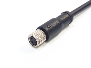
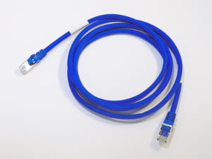
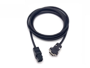
An operations manager at a growing OEM pulls up a spreadsheet of harness purchase orders from the past quarter and asks the question: What if we made these ourselves? The bill of materials looks manageable — wires, terminals, connectors, some conduit. The math seems promising. But between that spreadsheet and a reliable, field-ready wiring harness sits a manufacturing reality that goes far beyond cutting a few wires and crimping on some terminals.
What It Really Takes to Make a Wiring Harness
Making a production-grade wiring harness means executing a defined sequence of process steps, each with specific quality gates, under documented control. The core stages move from drawing interpretation through wire preparation, terminal crimping, connector assembly, bundling and protection, electrical and mechanical testing, to labeling and export-ready packaging. The most underestimated challenges are not in any single operation but in the disciplined verification between operations: confirming crimp settings at start of shift, checking strip dimensions after every reel change, and testing beyond a simple continuity beep. Skipping these verification points is what turns an apparent cost-saving exercise into a source of field failures and warranty exposure.
Step 1: From Drawing to Production Plan — The Overlooked First Step
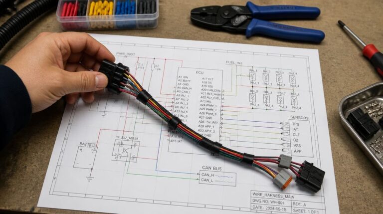
Manufacturing starts well before the first wire is cut. The harness drawing, bill of materials, and any customer-supplied test specification must be reviewed in detail. This review identifies wire gauge (AWG), insulation material, temperature rating, connector part numbers and cavity designations, terminal series, seal types, color codes, and any special marking requirements.
For automotive and heavy-equipment applications, low-tension primary cable defined by SAE J1128[1] governs insulation wall thickness, voltage rating, temperature class, and abrasion resistance for primary wiring used in surface vehicle electrical systems.
Common in-house mistakes at this stage include ignoring minimum bend radius requirements, misinterpreting branch length measurement points, or overlooking strain relief details at connector backshells. A harness that matches the schematic electrically but cannot be routed in the vehicle or machine due to a 20mm branch length error is a harness that stops the assembly line.
The output of this stage should be a first-article plan that defines the cutting list with lengths and tolerances, the crimp specification for each terminal series, the test sequence, and the inspection criteria. Without this document, the production team has no consistent reference for what “correct” looks like.
Step 2: Wire Preparation (Cutting and Stripping)
Wire preparation sets the dimensional foundation for everything that follows. Each circuit is cut to its specified length, with tolerance typically held to ±1% or the limits defined by IPC/WHMA-A-620 for the applicable product class. The strip length must match the terminal barrel length precisely — too short and the conductor will not fully engage the crimp barrel; too long and exposed conductor risks shorting to adjacent circuits.
The stripping operation must remove insulation cleanly without nicking or cutting individual conductor strands. Even a single nicked strand can create a stress concentration point that fractures under vibration, producing an intermittent open that is difficult to diagnose and expensive to repair in the field.
The choice between manual wire strippers and a semi-automatic cut-and-strip machine depends on the production context. The table below compares the key decision factors.
| Factor | Manual Wire Stripper | Semi-Automatic Cut-and-Strip Machine |
|---|---|---|
| Volume Suitability | Low volume, prototypes, field repairs | Medium to high volume production |
| Length Repeatability | Operator-dependent; requires frequent checks | Programmable; consistent within tight tolerances |
| Strip Quality Control | Varies by operator skill and fatigue | Adjustable blade depth; consistent results |
| Labor Cost per Piece | Higher at volume | Lower at volume; initial investment required |
| Setup Time | Minimal | Requires programming and blade adjustment per wire type |
Inconsistent wire lengths cause harness fitment issues during installation — branches that are too short will not reach their connectors, while overly long wires create slack that must be managed and can lead to chafing. The cost of reworking an assembled harness to correct a length error is far higher than the cost of verifying cut settings before production begins.
Step 3: Crimping Terminals — The Most Critical Process Control Point
Crimping is where the electrical and mechanical connection is formed between wire and terminal — and it is where most in-house wiring initiatives lose control of quality. A properly executed crimp creates a cold-welded, gas-tight connection that maintains low contact resistance throughout the harness service life. An improperly executed crimp may look acceptable but can produce either an intermittent open or a high-resistance joint that generates heat under load.
IPC/WHMA-A-620 defines acceptance criteria for crimps across three product classes, with Class 2 being the typical baseline for industrial and commercial harnesses. The standard addresses conductor crimp height and width, insulation crimp placement, the presence and dimensions of the bellmouth at the conductor crimp entrance, and minimum pull force values based on wire gauge. Crimp tooling must be set up and verified at the start of each shift, and crimp height measurements should be recorded periodically during the run.
A practical crimp verification sequence includes a pull test on sample crimps from the first pieces produced, visual inspection of the crimp profile under magnification for proper bellmouth formation and absence of excessive flash, and cross-section analysis when setting up a new terminal and wire combination. The pull test applies a known tensile force to the crimped connection; the wire should break before the terminal pulls off, with pull force meeting the IPC/WHMA-A-620 minimum values for the wire gauge.
An under-crimp, where the terminal barrel is not compressed enough, leaves voids that can corrode or loosen over time. An over-crimp fractures conductor strands inside the barrel, reducing the effective cross-section and creating a weak point. Both conditions can pass a simple continuity test but will fail later in service, often after the harness is installed in a difficult-to-access location.
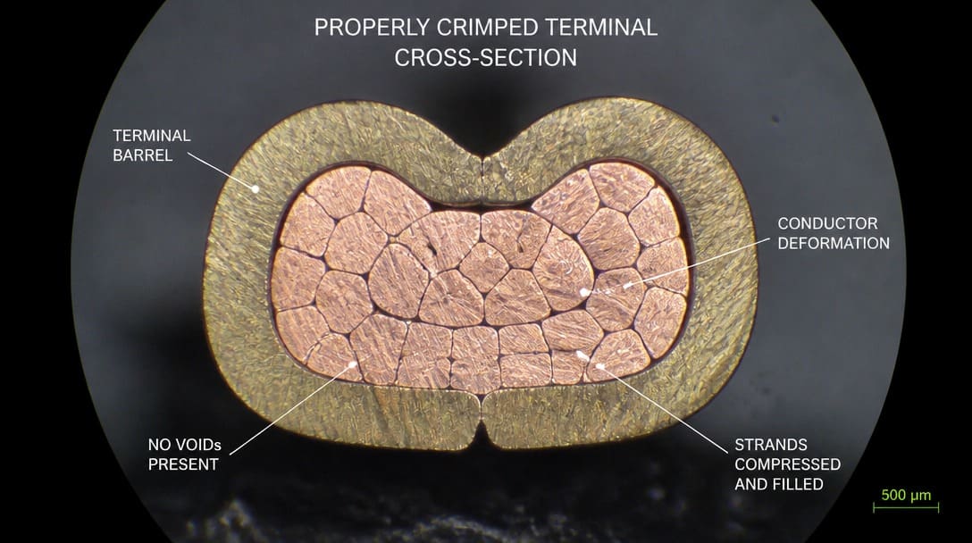
For OEM buyers who are evaluating whether to bring harness production in-house versus working with an experienced outside partner, the crimping station is the single most revealing point of comparison. Suppliers such as EDOM Electronics maintain crimp tool calibration records, conduct pull tests to IPC/WHMA-A-620 criteria, and perform cross-section verification when qualifying new terminal-and-wire combinations. That level of process discipline is what separates a harness that works on the bench from one that works for years in the field.
Step 4: Connector Assembly and Soldered Connections
Once terminals are crimped, they must be inserted into connector housings in the correct cavities and in the proper sequence. Each terminal should click audibly into its cavity and be verified with a gentle pull-back check. Incorrect insertion — a terminal not fully seated, or inserted into the wrong cavity — is one of the most common assembly errors and will be caught either at final test or, worse, during end-product assembly.
Strain relief and backshell assembly follow pin insertion. The backshell or strain relief clamp must grip the cable outer jacket or wire bundle securely enough to prevent any mechanical load from reaching the crimped terminations. A well-designed strain relief transfers pull forces to the connector shell rather than the terminal crimps.
Soldered connections have a limited role in industrial harness production. They are sometimes specified for low-volume, large-gauge power circuits or for repair situations, but crimping remains the preferred method for most production environments. Soldering introduces process variables that are harder to control than crimping: tip temperature, dwell time, solder alloy composition, and flux activity all affect joint quality. A cold solder joint — where insufficient heat prevents proper intermetallic bond formation — may pass initial continuity but develops high resistance or cracks under thermal cycling. When soldering is unavoidable, RoHS-compliant lead-free solder and appropriate flux must be used, with operator training and inspection focused on joint appearance, fillet formation, and absence of bridging between adjacent pins.
Step 5: Bundling, Sleeving, and Routing for Real-World Environments
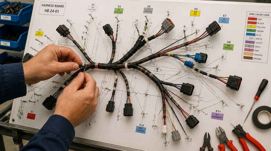
The outer protection of a wiring harness is not cosmetic — it directly determines how the harness survives vibration, abrasion, moisture, and installation handling. Breakout routing must maintain the exact branch lengths, orientations, and clocking angles defined on the drawing. A branch that leaves the main trunk 30mm too early or at the wrong angle may interfere with adjacent components or require stretching to reach its connector.
The choice of protective covering depends on the installation environment and serviceability requirements. Tape wrapping — whether point-to-point, spiral, or full coverage — provides flexibility and serviceability. Split conduit offers moderate protection with easier rework access, while braided sleeving delivers the highest abrasion resistance for demanding environments.
| Protection Method | Abrasion Resistance | Flexibility | Repairability | Typical Application |
|---|---|---|---|---|
| Tape Wrapping (fabric or PVC) | Moderate | Good | Easy — tape can be unwrapped | General industrial, appliance |
| Split Loom Conduit | Good | Moderate | Good — conduit can be opened | Automotive, engine compartments |
| Braided Mesh Sleeving | Excellent | Excellent | Poor — must be cut off to access | Robotics, aerospace, dynamic flex |
| Heat-Shrink Tubing | Good | Limited at thick walls | Poor — must be cut off | Connector transitions, sealing |
Routing errors — such as a wire bundle pulled taut across a metal bracket corner or a branch forced through an undersized grommet — create chafing points that abrade insulation over time. In vibrating installations, a single unprotected contact point can wear through insulation in months, creating a short circuit that is difficult to locate. The routing decisions made at the harness board directly determine the harness’s service life.
Step 6: Testing — Beyond a Simple Continuity Check
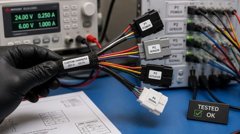
Testing a production harness requires more than confirming continuity from end to end. Three distinct test layers are needed to catch the failure modes that escape a basic beep test.
Continuity testing verifies that each circuit is wired to the correct pin and that there are no open circuits or shorts between adjacent pins. A proper continuity test uses a fixtured test board with mating connectors that allows every circuit to be checked simultaneously. Manual probing with a multimeter is too slow and too error-prone for volume production.
Pull testing confirms the mechanical integrity of each crimped or soldered termination. IPC/WHMA-A-620 defines minimum pull force values based on wire gauge, and the test should be performed on sample terminations from each production batch. A crimp that pulls out below the specified force indicates insufficient compression and will create intermittent opens in service.
Hi-pot (dielectric) testing applies a high voltage between circuits and between circuits and ground to verify insulation integrity. This test detects nicked insulation, insufficient creepage distances at connector terminations, and contamination that could lead to dielectric breakdown, particularly in higher-voltage or safety-critical circuits.
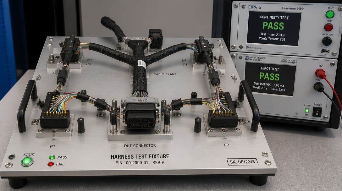
The field failure modes that most commonly trace back to inadequate testing include:
- Intermittent opens from under-crimped terminals that make partial contact until vibration separates the connection.
- Short circuits from insulation chafed through at an unprotected routing point.
- Miswiring from skipped or incomplete point-to-point checks, where circuits are connected to the wrong connector cavities.
- Dielectric breakdown from insulation damage that passes a low-voltage continuity test but fails at operating voltage.
Each of these failures can be prevented by a test regimen executed on properly fixtured equipment, with results documented for traceability.
Step 7: Labeling, Packaging, and the In-House Readiness Checklist
Labeling errors at the end of the harness build can undo all the process control that came before. Wire markers must be legible, correctly positioned, and matched to the drawing. Harness identification tags with unique part numbers and revision levels enable correct installation and future service. An illegible or missing label on a critical circuit creates confusion at the end-product assembly station and, if installed incorrectly, can cause system damage.
Packaging protects the completed harness through shipment, handling, and storage. Anti-static precautions apply when the harness includes sensitive electronic connectors. Coiling methods must avoid tight bends that stress terminations. For export shipments, packaging must account for humidity, handling cycles, and customs inspection — quality inspection and export packaging practices ensure the harness arrives in the same condition it left the production floor.
Before cutting the first wire, an in-house harness initiative should have the following minimum foundation in place. This checklist covers the essential equipment, quality verifications, and documentation required:
- Equipment: Cut-and-strip tooling with verified settings for each wire type; calibrated crimp tools with the correct dies for each terminal series; a pull tester capable of measuring to IPC/WHMA-A-620 force values; a continuity test fixture with mating connectors; a hi-pot tester if specified by the application.
- Quality Verifications: A first-article inspection plan defining the measurements and inspections for each production step; operator training on IPC/WHMA-A-620 acceptance criteria, with documented competency on crimp setup and inspection.
- Documentation: The approved harness drawing with revision level; a complete bill of materials with manufacturer part numbers for all connectors, terminals, seals, and wire; an inspection sheet listing the checks to be performed at each station, with space for operator sign-off and date.
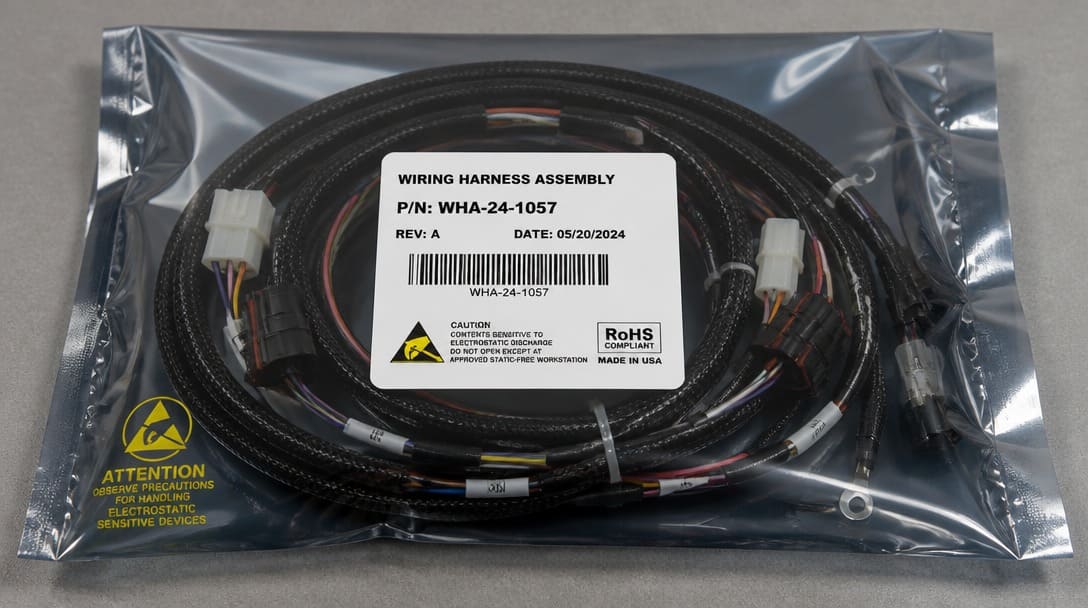
For OEMs comparing in-house harness manufacturing against outsourcing to a specialized production partner, the full picture extends beyond these production steps into supply chain management, connector sourcing, and the ability to absorb demand fluctuations. A partner that handles custom cable assembly and wire harness production from drawing review through export delivery can compress the learning curve that an internal team would otherwise climb project by project. The decision is rarely about capability alone — it is about the cost of process development, the risk of latent quality issues, and the opportunity cost of engineering time diverted from core product development.
In-House Manufacturing vs. Outsourcing: The Hidden Costs
Before investing in wire processing equipment, OEMs must evaluate the Total Cost of Ownership (TCO). While the raw material cost (wires, terminals) is transparent, hidden costs include:
- Tooling Calibration: Terminal applicators require strict calibration and maintenance.
- Component MOQ: Sourcing specialty connectors (e.g., TE Connectivity, Deutsch) often requires buying full reels (2,000+ pcs), locking up cash flow.
- Quality Assurance CapEx: A basic Hi-Pot tester and pull-force gauge setup can exceed $10,000. Partnering with an ISO-certified manufacturer like EDOM Electronics eliminates these CapEx barriers while guaranteeing IPC-620 compliance.
Frequently Asked Questions
What is the minimum equipment needed to start making wiring harnesses in-house?
The absolute minimum includes a cut-and-strip tool (manual or semi-automatic depending on volume), crimp tools with the correct dies for the terminal series being used, a continuity tester, and a pull tester to verify crimp strength against IPC/WHMA-A-620 values. A hi-pot tester becomes necessary if the harness operates at higher voltages or in safety-critical applications. Beyond equipment, the team needs access to the approved drawing, bill of materials, and inspection criteria before any production begins.
Why is crimping preferred over soldering for wire harness connections?
Crimping produces a consistent, gas-tight cold weld between the wire conductor and the terminal barrel when performed with properly set-up tooling. The process is faster than soldering, does not introduce heat-related insulation damage, and produces results that are more repeatable across operators. Soldering introduces variables — tip temperature, dwell time, alloy composition — that are harder to control, and a cold solder joint can pass visual inspection while creating a latent reliability risk.
How do I verify that a crimp is acceptable before full production?
Verification starts with a pull test on sample crimps to confirm the force required to separate the wire from the terminal meets IPC/WHMA-A-620 minimums for the wire gauge. Visual inspection under magnification checks for proper bellmouth formation, absence of excessive flash, and correct insulation crimp placement. For new terminal-and-wire combinations, a cross-section analysis confirms proper conductor deformation and barrel fill. Crimp height should be measured and recorded at start of shift and periodically during the run.
What are the most common causes of harness failure in the field?
Intermittent opens from under-crimped terminals that make partial contact until vibration breaks the connection. Short circuits caused by insulation chafed through at unprotected routing points where the harness contacts sharp edges or brackets. Miswiring from skipped or incomplete point-to-point continuity checks where circuits are connected to the wrong connector cavities. And dielectric breakdown from insulation damage that passes a low-voltage continuity test but fails at operating voltage under real-world conditions.
When does it make sense to outsource harness production instead of making it in-house?
The decision typically turns on volume, complexity, and the cost of developing internal process control. Low-volume, simple harnesses with a few circuits may be practical to produce in-house with basic equipment and training. However, as circuit count increases, terminal types multiply, or testing requirements become more stringent, the investment in tooling, fixturing, operator training, and quality documentation grows quickly. A production partner that already maintains calibrated tooling, documented processes, and multi-layered testing capability can deliver reliable harnesses without the overhead of internal process development.
Key Takeaways
- Harness manufacturing begins with a thorough drawing and BOM review — dimensional details, connector part numbers, insulation standards such as SAE J1128 and UL requirements, and test specifications must all be resolved before cutting the first wire.
- Crimping is the single most critical process control point; daily tool verification with pull testing and crimp height measurement to IPC/WHMA-A-620 criteria is essential for reliable connections.
- Testing must go beyond continuity — pull testing verifies mechanical crimp strength, and hi-pot testing detects insulation defects that continuity checks cannot find.
- Routing and protective covering choices directly affect service life; unprotected contact points in vibrating environments create chafing failures that are expensive to diagnose and repair.
- The in-house readiness checklist — equipment, quality verifications, and documentation — defines whether an internal harness initiative is set up for consistent quality or for latent warranty exposure.
For a closer look at how a dedicated production partner manages the full harness manufacturing process — from design review and connector sourcing through inline inspection and export-ready packaging — visit the wire harness manufacturing overview for additional guidance on evaluating build partners against the requirements outlined here.