An SFP transceiver does not use one connector; it uses two connector systems — the host-board electrical interface and the front-panel media port. Most sourcing mistakes come from treating them as a single “SFP connector.”
Direct Answer: An SFP transceiver uses two connector systems, not one: on the host board, a 20-pin edge-card cage and connector interface compliant with INF-8074i (legacy 1G SFP) or SFF-8431 / SFF-8472 (10G SFP+) provides the electrical signal path; on the front panel, an LC duplex optical connector serves common fiber modules, an RJ45 (8P8C) serves copper transceivers, and specialty links utilize SC or MPO.
Host-Board SFP Connector: The 20-Pin Cage and Edge-Card Interface
The host-board interface is a 20-pin edge-card style connector mounted inside a metal cage. The SFP transceiver slides into the cage and mates with the host PCB through the cage connector, not through a traditional plug-and-receptacle pair in the cable sense. The cage itself is the mechanical retention and shielding system: it mounts to the board through through-hole or surface-mount solder tails and includes EMI shielding fingers, latch features, and often heat-sink or lightpipe features that must match the board layout and panel cutout.
SFF-8431/INF-8074i define the electrical and mechanical requirements for SFP/SFP+ cages and connectors. MSA (Multi-Source Agreement) compliance establishes that the module and cage share the same baseline form factor, but it does not guarantee interchangeability between every cage and every transceiver. A 1G SFP transceiver and a 10G SFP+ transceiver share the same 20-pin mechanical form factor; the differences show up in speed rating, signal-integrity requirements, high-speed pad layout, and recommended cage or connector construction. That is why a generic “SFP connector” cannot confirm pinout or speed class without the mating transceiver part number and cage drawing number.
Media-Side Connector by SFP Variant: LC Duplex, RJ45, and Specialty Options
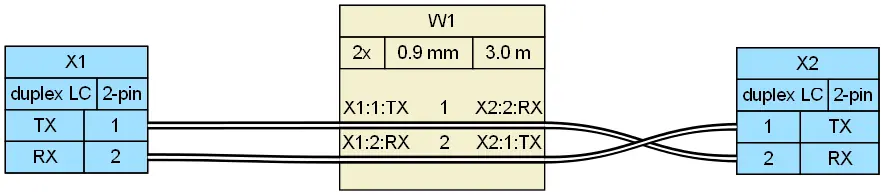
Once the host side is confirmed, the second connector system appears at the front panel. Fiber SFP and SFP+ transceivers use a duplex LC connector: two fibers, one for transmit and one for receive. The typical optical polish is PC or UPC, and patch-cord polarity must follow A-B routing so the transmit fiber at one end lands on the receive fiber at the other. A duplex LC connector with the correct polish and polarity is often the physical difference between a working link and a dark port.
| SFP Variant | Front-Panel Connector | Typical Link | Key Confirmation |
|---|---|---|---|
| Fiber SFP/SFP+ (dual fiber) | Duplex LC | 1G/10G optical links | PC/UPC polish (standard dual fiber); APC for specific BiDi/single-fiber WDM links; A-B (crossover) polarity verification |
| Copper SFP | RJ45 (8P8C) | 1000BASE-T twisted pair | Cat5e, Cat6, or Cat6A cabling and link speed support |
| Specialty optical | SC or MPO | Legacy/long-reach or multi-fiber | Confirm from transceiver datasheet; not a default assumption |
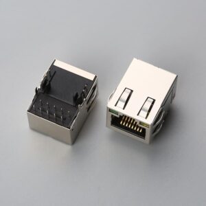
Copper SFP modules use an RJ45 port instead of a fiber connector. The RJ45 copper SFP uses the 8P8C interface with T568A/T568B wiring for twisted-pair Ethernet links such as 1000BASE-T. No LC connector is involved, and the RJ45 port must support the module’s link speed and the installed Cat5e, Cat6, or Cat6A cabling plan. Specialty variants may use SC connectors for legacy or single-fiber optical designs and MPO for multi-fiber applications. These are not the default; they must be confirmed from the transceiver datasheet. Note that standard dual-fiber transceivers mandate UPC polish (blue boots), while BiDi or PON modules frequently require angled APC polish (green boots). Never mate a UPC cable into an APC port, as the angled physical mismatch causes severe optical return loss and permanently chips the ceramic ferrules.
To read the transceiver datasheet correctly, look for the “connector type” or “media interface” specification. It states whether the front panel is duplex LC, RJ45, SC, or MPO. If the BOM lists only the SFP transceiver and not the front-panel cable, do not assume LC. A copper SFP module has an RJ45 opening and cannot accept an LC connector.
What “Compatible” Means for SFP Connectors: One Mated System, Not a Drop-In Part
SFP connector compatibility is a system requirement. The transceiver, cage or host connector, host PCB, and cable or optic must be specified as one mated set. A missing mating part number for the transceiver, cage, or cable means the connector cannot be confirmed or quoted as a true drop-in replacement.
MSA compliance covers the baseline form factor, but it leaves room for design-specific differences in latch geometry, EMI finger style, heat-sink height, board footprint, and panel cutout. These details require drawing-level confirmation. Procurement RFQs should list the transceiver manufacturer and part number, the cage drawing or part number, and the media cable connector type. Otherwise connector matching stops at drawing review. Suppliers such as EDOM Electronics support OEM buyers with requirement review, connector matching, sample coordination, production follow-up, inspection, and export-ready packaging for custom cable assemblies and high-speed interconnects. For SFP-related projects, that includes clarifying whether the “SFP connector” line refers to a host-side cage, a media-side patch cord, or both.
If a “compatible” cage is priced far below the OEM cage, verify plating, EMI finger spring force, latch retention, and signal-integrity construction before accepting it. A low-cost cage can pass a visual check and still create grounding, EMC, or retention failures.
SFP Connector Failure Modes We See in the Field
We regularly see SFP connectors pass visual incoming inspection but fail when the module won’t latch, the cage fingers collapse, or the LC patch cord unlatches in the rack — the cage or cable was bought as a drop-in without confirming the mating part number.
- Wrong LC polish or polarity: Mismatched UPC/APC end faces can cause insertion loss exceeding 0.5 dB and return loss degradation below 30 dB, risking optical interface damage. Polarities must verify Tx-to-Rx A-B crossover per TIA-568 standards.
- Collapsed cage EMI shielding fingers: Deformed beryllium copper fingers compromise chassis grounding (target contact resistance typically < 30 mΩ), causing radiated emissions failures during FCC/CE EMC compliance testing.
- Substandard contact plating and mechanical wear: Inferior gold plating (e.g., flash plating < 15 µin vs. standard 30 µin hard gold) leads to micro-fretting corrosion, raising contact resistance after fewer than 100 mating cycles.
- 1G cage vs. 10G SFP+ high-speed signaling mismatch: While mechanically identical, older 1G connector pin footprints lack signal-integrity tuning, introducing excessive insertion loss and differential cross-talk at 10.3125 Gbps.
- Module retention latching failure: Inadequate latch retention force (failing the typical 90 N axial retention threshold) causes link drops under cable strain relief pull force or chassis fan vibration.
- Thermal dissipation bottleneck: High-power optical transceivers (> 1.5W, such as 10G ZR or copper 10GBASE-T modules) in unvented cages without integrated riding heat sinks exceed the 70°C case limit, triggering thermal shutdown.
SFP Connector Verification Checklist Before Ordering
Before an RFQ or purchase order is released, confirm the following six items. A missing answer does not mean “assume standard”; it means the connector cannot yet be confirmed as a mated system.
| Check | What to Confirm | Expected Confirmation |
|---|---|---|
| 1. Host side vs media side | Identify whether the requirement is for the host-board 20-pin cage/connector or the front-panel LC, RJ45, SC, or MPO interface. | Clear split between host and media connector systems |
| 2. MSA electrical standard | Confirm SFF-8431/INF-8074i compliance for the SFP/SFP+ cage and connector. | Standard reference stated on drawing or datasheet |
| 3. Speed and pin count | Confirm the 20-pin mechanical form and whether the link is 1G SFP or 10G SFP+; signal requirements differ by speed class. | Transceiver speed class named |
| 4. Cage mounting and thermal features | Confirm through-hole or SMT solder tails, panel cutout, EMI finger geometry, and heat-sink or lightpipe features. | Cage drawing number and revision |
| 5. Media connector type and polish/polarity | Confirm duplex LC PC/UPC with A-B polarity for fiber, or RJ45 for copper. | Cable or patch-cord specification |
| 6. Mating part numbers | Confirm transceiver part number, cage drawing, and media cable connector type. | Transceiver datasheet page and cage drawing available |
Before you quote or build, confirm the mating transceiver part number, cage drawing, and media cable connector type. If any one of these is missing, the SFP connector cannot be confirmed as a true mated system.
From SFP Connector Verification to Production-Ready Interconnects
After the host cage, transceiver, and media cable are confirmed, the next step is a full interconnect review. For custom cable assemblies that connect to SFP media ports, specify duplex LC polarity and polish or RJ45 termination clearly in drawings and samples. For OEM hardware engineers integrating SFP/SFP+ ports, resolving the interconnect bill-of-materials early avoids production respins. Whether you require precision 10G SFP+ passive Direct Attach Copper (DAC) assemblies with tuned twinaxial impedance (100 ± 5 Ω), or ruggedized industrial IP67 LC duplex patch cords with reinforced breakout strain relief, EDOM Electronics provides full DFM analysis, pin-to-pad SI review, and rapid first-article prototypes in 3 to 5 business days.
The same SFP verification checklist can be used as an incoming quality or sourcing check for OEM, distributor, and trader programs. Once the host cage, transceiver, and media cable are confirmed, the remaining work is production follow-up, inspection, and export-ready packaging. Quality inspection and export packaging processes should include continuity testing, visual inspection of EMI fingers and LC end faces, and packaging that protects latches and polished surfaces during shipment.
For practical electronic connector sourcing, custom cable assembly review, and interconnect support, explore electronic connector sourcing options.
Frequently Asked Questions
Do SFP and SFP+ transceivers use the same host-board connector?
Yes, 1G SFP and 10G SFP+ transceivers share the same 20-pin mechanical form factor. However, speed class changes the signal-integrity requirements and recommended cage or connector construction, so the mating part numbers and cage drawing should still be confirmed.
How can I tell whether an SFP transceiver needs an LC or RJ45 connector?
Check the transceiver datasheet for the “connector type” or “media interface” specification. Fiber SFP/SFP+ modules normally show duplex LC; copper SFP modules show RJ45; specialty variants may list SC or MPO. The physical port can also be inspected: an LC opening is square with two fiber positions, while an RJ45 opening is wider and accepts an 8P8C plug.
What information should an RFQ include for an SFP connector?
List the transceiver manufacturer and part number, the cage drawing or part number, the host-board mounting style, and the media cable connector type with polish and polarity. Without these references, a supplier cannot confirm whether the requirement is for a host cage, a patch cord, or both.
Does MSA compliance mean any SFP cage works with any SFP transceiver?
No. MSA compliance establishes the baseline form factor, but latch geometry, EMI finger style, heat-sink height, board footprint, and panel cutout still require drawing-level confirmation. A compatible cage is a mated system decision, not a drop-in part.
Why does LC polish or polarity matter if the connector physically fits?
PC and UPC polished end faces can create different return-loss behavior, and A-B polarity reversal means the transmit fiber does not land on the receive fiber at the far end. The physical connector can fit and still produce low light or no link.
Key Takeaways
- An SFP transceiver uses two connector systems: a 20-pin host-board SFP/SFP+ cage and connector compliant to SFF-8431/INF-8074i, and a front-panel media interface.
- Fiber SFP/SFP+ modules use duplex LC with PC/UPC polish and A-B polarity; copper SFP modules use an RJ45 8P8C port; specialty variants may use SC or MPO.
- Compatibility is not a single part number. The transceiver, cage or host connector, host PCB, and cable or optic must be specified as one mated set.
- Before ordering, confirm host side vs media side, compliance standard, speed class, cage mounting and thermal features, media connector type and polish/polarity, and all mating part numbers.
- Visual inspection alone cannot catch many SFP connector failure modes, including wrong LC polarity, collapsed EMI fingers, poor cage plating, and speed mismatch.