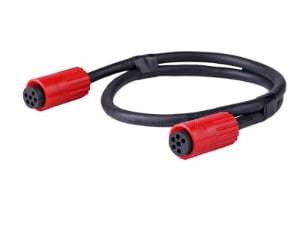
A low-voltage installer opens a sealed box of pre-terminated assemblies on a Friday afternoon and finds the RJ45 shells are floating—every data line locks up when the rack powers on. The continuity report in the box says every pin passed. What the report doesn’t show is the ungrounded shield, the pierce in the jacket from an insulation support tab, or the crimp that drifted just enough to heat under load.
Direct answer: A pre-terminated cable assembly(covered in our What Is a Cable Assembly? Definition, Components, and Applications guide) is a factory-terminated cable and connector assembly with documented crimp, insulation, and shielding verification, used to eliminate field termination errors at the install site. Where to buy pre-terminated cable assemblies for installers: source from a manufacturer that documents IPC/WHMA-A-620 workmanship, pulls first-article samples with hi-pot and pull-force data, and asks about the install environment before quoting—not a distributor moving commodity stock.
Sourcing Route Decision: Factory-Direct vs. Catalog Distributor
- Catalog Distributors (DigiKey, Mouser, RS): Best for standard patch cords, off-the-shelf catalog lengths (<100 pcs), and emergency overnight maintenance where pinouts and potting are standardized.
- Direct Custom Assembly Manufacturers: Critical for non-standard lengths, custom overmolded strain reliefs, fieldbus/hybrid breakouts, IP67/IP68 submersible potting, and projects requiring IPC/WHMA-A-620 Class 3 serialized pull-test and hi-pot test reports.
Why a Continuity Pass Is Not Field-Readiness Proof
Continuity testing confirms that an electrical path exists from pin to pin. It does not confirm that the assembly will survive the install site. A pre-terminated assembly is only terminated off-site; it is not automatically tested to the vibration, moisture, flexing, and grounding conditions of the installation.
Three failure modes routinely hide behind a continuity pass:
- Floating connector shells — an RJ45 shell that is not bonded to ground can act as an EMI antenna and produce intermittent faults only when the rack powers on under load.
- Insulation support tabs piercing the jacket — a strip length error or over-tight insulation tab creates micro insulation damage that passes bench continuity but opens a moisture path in the field.
- Crimp height drift — a crimp that is slightly loose or tight may still conduct at low current, but contact resistance rises under load until the housing melts after the installer has left the site.
Continuity testing alone misses all three conditions because it never stresses insulation, never pulls on terminations, and never checks shield bonding. The buyer’s acceptance criteria, not the continuity report, is what prevents these failures.
How to Qualify a Supplier Before Ordering
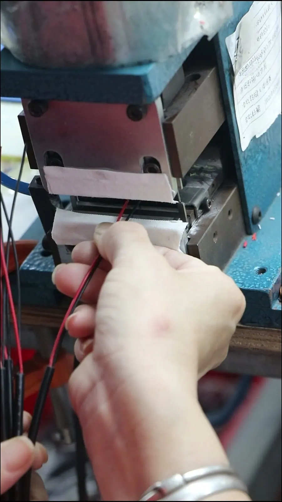
Supplier qualification for pre-terminated cable assemblies starts with test evidence, not price. Before accepting a quotation, require crimp-height verification records, pull-force data, and cross-section photos from first-article samples. Ask whether the supplier works to IPC/WHMA-A-620 Class 2 or Class 3 workmanship criteria and whether hi-pot and pull-force data(review the Top 10 Electrical Specifications for Cable Assembly & Wiring Harness guide) come from the specific assembly being quoted, not a generic family datasheet.
IPC/WHMA-A-620 defines three workmanship acceptance classes, each with distinct inspection and documentation requirements. Class 3 applies where intermittent failure could cause loss of function in critical installations; Class 2 suits general industrial use. A supplier that cannot state which class it works to has not yet separated assembly practice from commodity cable selling.
“When an inquiry arrives for a pre-terminated assembly with only a length and a connector photo, we have to stop and ask about moisture, flexing, and grounding. Each clarification round adds days to delivery.”
Treat distributor stock as an equal substitute only if the distributor can provide the same test evidence and environmental review. A sealed bag from a warehouse does not replace first-article validation for the install site.
Specifying the Assembly for the Install Site
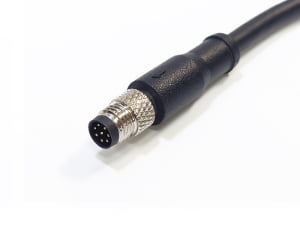
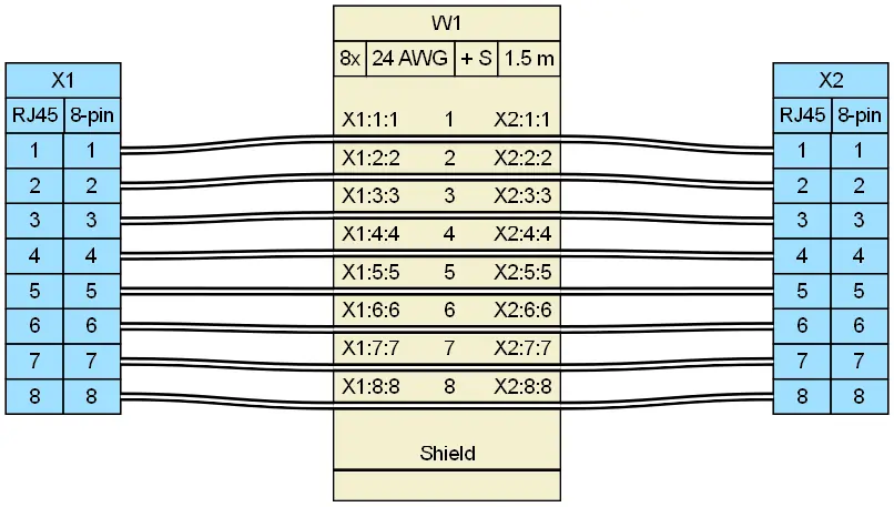
Turning the install environment into a specification is the buyer’s most direct risk control. Start with connector type and field termination. M12 connectors, used for industrial sensing and actuation, follow IEC 61076-2-101 for dimensional and performance expectations. M8 connectors provide a compact alternative for sensor-level connections where routing space is tight. RJ45 uses the 8P8C interface with T568A or T568B wiring for Ethernet data runs, and the same pinout must be used at both ends.
Declare cable jacket rating, operating temperature, moisture/UV exposure, and maximum pull tension before quoting. These variables change conductor material, shielding construction, and overmold selection. Specify IP67 sealing(see Waterproof Cable Assembly Manufacturing & Supply for OEM Buyers) where dust ingress or temporary immersion would compromise the termination—washdown, outdoor, and conduit-free runs all qualify. Also state whether connector shells must be bonded to system ground, floated at one end, or isolated. Leaving grounding to assembly default is the most common cause of floating shell faults.
For industrial power and control cable assemblies feeding machinery, UL 2238 provides safety constraints on connectors and fittings. The standard is not a replacement for environmental specification, but it helps confirm that power-carrying assemblies are evaluated for the intended load and construction category.
| Connector type | Typical install use | Relevant standard or interface | Termination/wiring notes |
|---|---|---|---|
| M12 | Industrial sensing, actuation, fieldbus | IEC 61076-2-101 dimensional and performance | A-coded, B-coded, or D-coded depending on signal type; sealing typically IP67 |
| M8 | Compact sensor-level connections, tight routing | IEC 61076-2-104 (Circular connectors with M8 screw-locking or snap-locking) | 3 to 4 poles typical; verify pin count against sensor I/O |
| RJ45 | Ethernet data runs, rack and endpoint connections | 8P8C interface with T568A or T568B pinout | Same pinout both ends; confirm shield bonding separately |
Test Evidence to Demand Beyond Continuity
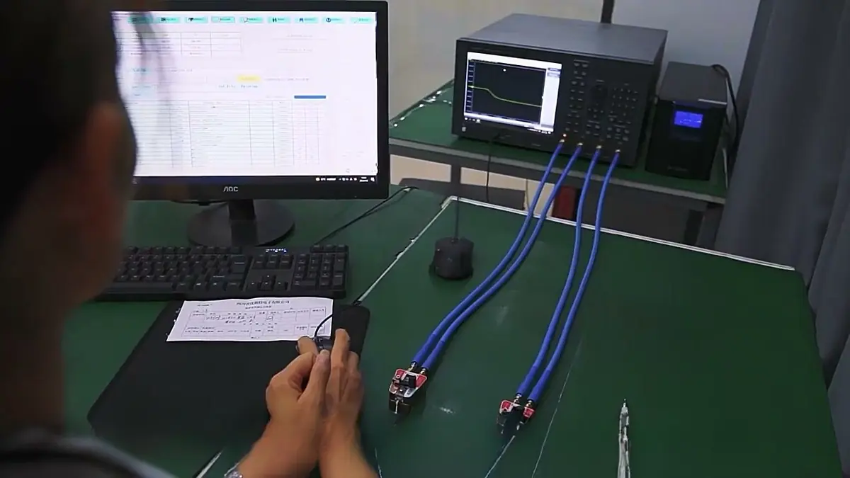
A one-line continuity report is not a test package. Three additional evidence types separate field-ready pre-terminated assemblies from commodity terminated cables:
- Hi-pot testing catches micro insulation nicks, jacket breaches, and moisture paths that continuity cannot see because it never stresses insulation between conductors and shield.
- Periodic destructive pull tests confirm crimp and terminal retention under install tension. A pull-force record exposes crimp height drift before the terminal backs out or the housing melts under load.
- Shield termination checks identify floating connector shells and hard-grounding both braid ends. Bonding one end and floating the other reduces ground loops; the test report must show which condition was built.
The table below compares what each test actually verifies and what field failure it prevents.
| Test | What it verifies | Field failure it catches | Why continuity misses it |
|---|---|---|---|
| Continuity | Electrical path from pin to pin | Open circuits | No insulation stress, no pull force, no shield check |
| Hi-pot | Insulation integrity under high voltage | Micro nicks, jacket breaches, moisture paths | Continuity only passes low-current signal path |
| Pull-force | Crimp and terminal retention | Terminals backing out under install tension | Continuity stays until motion or load is applied |
| Shield termination | Shield bonding and grounding path | Floating shells, EMI lockups, ground loops | Continuity checks signal conductors only |
Field Failure Patterns That Start at the Purchase Order
Each failure mode below can be traced back to a buying decision—not an installer error:
- Floating connector shells act as EMI antennas and cause lockups when racks power on. The purchase order failed to specify shell grounding.
- Micro insulation damage from incorrect strip length or over-tight insulation tabs passes bench continuity but fails under vibration and moisture. The supplier was never asked for cross-section photos or hi-pot data.
- Ground loops from hard-grounding both braid ends induce noise and can damage equipment. The assembly defaulted to both-end bonding because the buyer did not state a grounding scheme.
- Crimp height drift raises contact resistance until housings melt under load, often after the installer has left the site. Crimp-height verification and pull-force records were not required before production.
Treating supplier evidence as a risk control, not paperwork, closes each of these gaps before tooling is set.
Pre-Purchase Checklist for Installers
The checklist below condenses the four buying decisions into a single RFQ screen. Send it with every pre-terminated cable assembly inquiry.
| Checklist item | What to specify or require |
|---|---|
| Operating environment disclosed | Indoor dry, outdoor, washdown, vibration, flexing, UV, and maximum pull tension |
| IP rating specified | IP67 where moisture ingress would compromise termination |
| Shell grounding specified | Bond one end, float the other, or isolate—do not leave this to assembly default |
| Test reports required | Hi-pot, pull-force, cross-section photos, and shield termination verification |
| Lead time confirmed | Against first-article sample approval, production, inspection, and export packaging |
Mid-article check: Send this checklist with your next RFQ. If the supplier cannot answer the three test questions—hi-pot, pull-force, shield termination—keep looking.
From First-Article Approval to Export-Ready Delivery
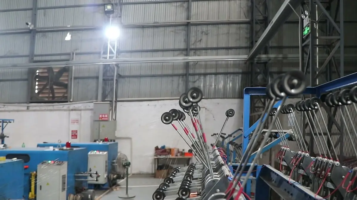
Once a supplier passes the qualification screen, the working process should follow a fixed sequence. Confirm first-article samples before full production and review cross-section photos and test data against the install environment. Schedule production follow-up to lock crimp settings, connector matching, labeling, and looming after sample approval—a control that ties directly to wire harness manufacturing discipline.
Require continuity and appearance inspection plus final verification before export packaging. Packaging should preserve termination orientation, prevent connector damage, and include labeling that matches the buyer’s receiving process. The same discipline applies to quality inspection and export packaging used for OEM shipments.
For installation contractors and OEM procurement teams, mitigating these failure modes requires partnering with an assembly manufacturer that integrates upfront DFM (Design for Manufacturability) reviews, dedicated crimp micro-section validation, and rapid 3-to-5 day first-article prototyping. EDOM Electronics structures this exact workflow—aligning connector pinouts, overmold strain-relief tooling, and calibrated pull/hi-pot testing before full-scale production runs are scheduled.
Frequently Asked Questions
What is the difference between a continuity test and a hi-pot test on a pre-terminated cable assembly?
Continuity verifies that current flows from pin to pin, but it does not stress insulation. A hi-pot test applies high voltage between conductors and shield to expose micro nicks, jacket breaches, or moisture paths that continuity cannot detect.
Should installers buy pre-terminated cable assemblies from a distributor or a manufacturer?
A manufacturer that documents IPC/WHMA-A-620 workmanship and supplies crimp height, pull-force, and shield termination data is usually a safer choice. Distributors can be acceptable if they provide the same test evidence and can answer environmental questions before quoting.
How do I specify IP67 for a pre-terminated M12 assembly?
State IP67 as the minimum sealing requirement for washdown or outdoor exposure. Also specify whether the connector shell must be bonded to system ground, because sealing does not automatically solve grounding.
What does IPC/WHMA-A-620 Class 2 vs Class 3 mean for installers?
IPC/WHMA-A-620 defines three workmanship classes with increasing inspection and documentation rigor. Class 3 applies to products where intermittent failure could cause loss of function in critical installations; Class 2 suits general industrial use.
What causes a connector shell to feel live?
A floating shield or missing ground bond can leave the shell at a different potential from system ground. That creates EMI susceptibility and can produce intermittent data faults, especially when racks power on.
Key Takeaways
- “Pre-terminated” does not mean field-verified. Acceptance must include hi-pot, pull-force, and shield termination evidence beyond continuity.
- Qualify the supplier before the quote: require crimp-height verification records, cross-section photos, and a stated IPC/WHMA-A-620 workmanship class.
- Specify connector type, IP rating, shell grounding, temperature, moisture, UV, and pull tension before the supplier begins drawing review.
- Floating shields, micro insulation damage, ground loops, and crimp drift are purchasing failures, not installer errors.
- First-article approval, production follow-up, final inspection, and export-ready packaging complete the risk-control loop.
Installers and procurement leads who need specification review, sample coordination, and export documentation can explore custom cable assembly solutions built around first-article verification and field-preventive test evidence.