A maintenance engineer opens a 15-year-old CNC machine panel and sees a loose video connector labeled “VGA” on the wiring diagram. He orders a replacement 15-pin connector from stock—only to find it won’t plug in. The pin pattern looks right, but the shell is too wide. This article explains what a VGA connector actually means on a drawing, why not all 15-pin connectors are VGA, and the four non-negotiable checks that separate a working replacement from a line stoppage.
At a Glance
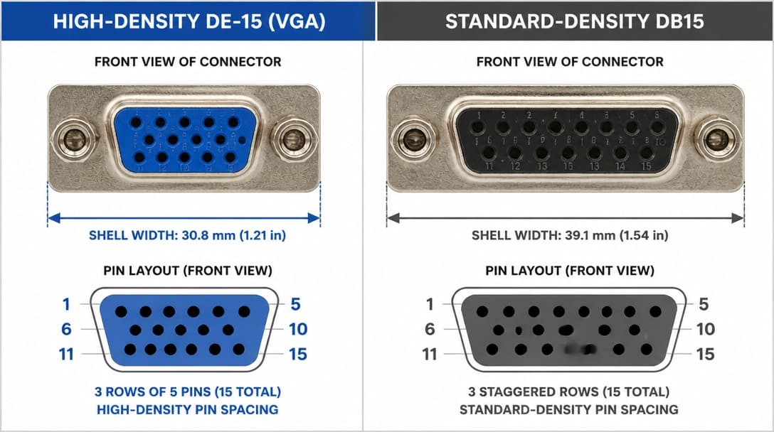
A VGA connector is a high-density DE-15 interface—three rows of five pins in an E-size shell—defined by the VESA DDC standard for analog video. It is not the larger, two-row DB15 connector often confused for it. Despite both having 15 pins, physical interchange is impossible, and misidentification leads to mechanical mismatch. Verifying pin density, shell dimensions, and gender is the only way to ensure OEM compatibility.
What Exactly IS a VGA Connector? It’s Not Just Any 15-Pin D-Sub
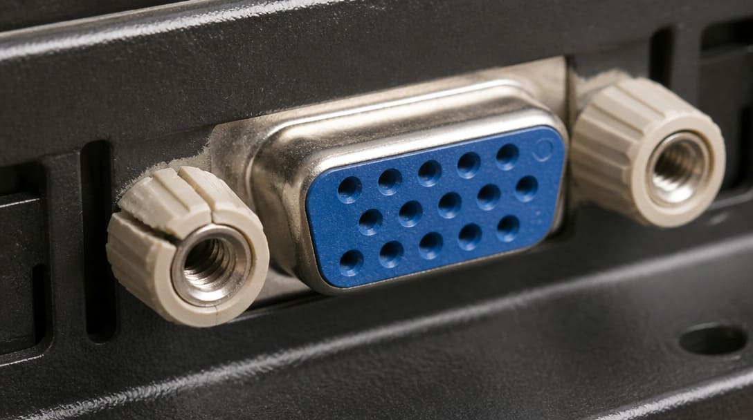
The core of the confusion lies in the shell. A VGA connector uses a DE-15 shell—the same width as a 9-pin DE-9 but deeper, accommodating three staggered rows of five pins each. The standard-density DB15, by contrast, has two rows of pins in a wider B-size shell. When a drawing or BOM merely lists “15-pin D-sub,” procurement is already at risk. The physical footprint is different, the panel cutout dimensions are different, and the mating interface is mechanically incompatible.
Gender assignment follows a predictable convention: equipment panels and PCB-mounted receptacles are female, while cable-end plugs are male. This is the opposite of many other connector families, and assuming the opposite leads to costly assembly rework. A lesser-known variant, the mini-VGA, appears on some legacy laptops but is electrically and mechanically distinct, adding another layer of caution for buyers sourcing replacements based on photos alone.
The VESA Display Data Channel (DDC) standard uses specific pins on the DE-15 for monitor identification and EDID communication. While the video signal is analog, the presence of DDC means that a connector not manufactured to the correct pinout compromises plug-and-play functionality. The connector is not simply a passive conduit; its pin mapping is part of the system specification.
The Three Specifications Your BOM Forgets to Mention
Even when a BOM correctly identifies a VGA connector, it rarely captures the three dimensions that determine whether the part can be assembled without incident. Absent these details, a connector that looks identical in a catalog can halt a production line.
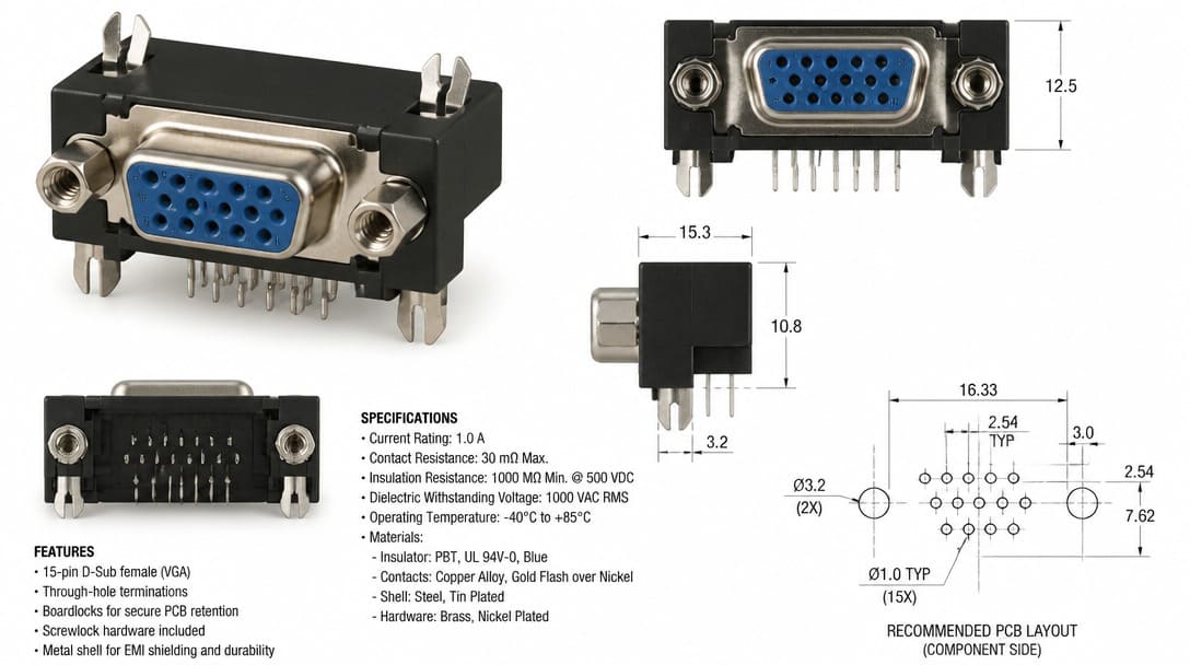
Termination method. PCB-mounted VGA connectors come in through-hole, surface mount, right-angle, or straddle-mount configurations. For cable assemblies, the choice is between solder cup and crimp contacts. Each demands a distinct tooling and process flow. Ordering a solder cup version when the assembly house only has crimp tooling is a schedule killer. Connector manufacturers such as TE Connectivity and Amphenol publish comprehensive termination drawings that specify hole diameters, pad layouts, and coplanarity tolerances—data that generic suppliers often omit.
Mounting hardware. The screwlock thread is not universal. Common variants include 4-40 UNC, M2.5, and M2.6. Thread length and standoff height determine whether the connector sits flush against the panel cutout and whether the PCB can be secured without warping. Boardlocks—integrated metal tabs or molded posts—are not cosmetic. They anchor the connector body to the PCB, preventing movement during soldering and relieving strain on the signal pins. A connector missing boardlocks where the footprint expects them will float during wave solder, generating open joints and intermittent failures.
Plating stack. The difference between selective gold on the contact area and full gold flash across the entire pin is not trivial. A selective gold plating with a proper nickel underplate ensures reliable mating durability and solderability. Full gold flash on a tin-lead solder tail creates brittle intermetallics and cold joints. EIA-364[1] test methods define the required plating thickness and porosity limits for connector contacts; assembly floors see the result when insufficient nickel underplate leads to corrosion or when the wrong flash chemistry prevents wetting.
When ‘Compatible’ Becomes a Production Hazard
The term “compatible” is dangerously ambiguous. A connector that mates electrically with a VGA receptacle may still be a production hazard. Mating-face interchangeability says nothing about the connector’s ability to survive the manufacturing process.
Consider wave soldering. The connector body must be manufactured from a plastic rated for preheat temperatures above the solder pot. UL 94 flammability classification alone does not guarantee thermal stability. If the plastic softens or distorts, pin coplanarity is lost and solder bridges form. For surface mount assemblies, the connector must withstand reflow profiles without warping. Branded connectors from Molex, Hirose, or TE Connectivity are qualified to these conditions with documented process windows. Unbranded equivalents frequently skip this qualification, turning a saving of a few cents per part into an entire shift of rework.
Standoff height is another hidden variable. Connectors with a standoff that is too short prevent full insertion into the PCB, leaving a gap under the body that produces floating solder fillets. Those with a standoff that is too tall push the connector face beyond the panel cutout, preventing the screwlocks from engaging. Both conditions are invisible during visual incoming inspection and only emerge during final assembly.
RoHS compliance adds a layer of chemical compatibility. Plating chemistries changed when lead was eliminated, and not all connector finishes bond equally well with lead-free solders. The interaction between the connector’s terminal plating and the assembler’s solder paste must be validated, not assumed.
The VGA Connector Validation Checklist
Before any VGA connector enters the kitting bin, the items in the table below should be verified against the manufacturer’s datasheet and the actual assembly requirements. This checklist closes the gap between a generic catalog description and a production-ready component.
| Check Item | Specifications to Confirm | Potential Risk if Missed |
|---|---|---|
| Connector Density | DE-15 (3 rows of 5 pins, E-size shell); not DB15 | Physical mismatch; connector won’t fit panel cutout or mate |
| Gender at Connector Face | Male on cable ends, female on panel/PCB receptacles | Mating impossible; reordering and rework |
| Termination Style | Through-hole, SMT, solder cup, or crimp contacts | Assembly process incompatibility; tooling gap |
| Screwlock Thread & Length | 4-40 UNC, M2.5, M2.6; length to pass panel and engage threads | Cannot secure connector; intermittent video under vibration |
| Boardlock Requirement | Presence and type of boardlocks per PCB footprint | Connector float during soldering; broken solder joints |
| PCB Footprint Match | Pad layout, hole sizes, and standoff height per datasheet | Poor fit, solder shorts, mechanical stress on solder fillets |
| Plating Specification | Selective gold contact area, nickel underplate thickness, tail plating | Solderability failure, corrosion, premature wear |
| RoHS Status | RoHS-compliant materials and finishes | Non-compliance in export markets; solder process mismatch |
When VGA connectors are part of a custom cable assembly, this validation becomes one step in a larger build process. Suppliers such as EDOM Electronics can support OEM buyers with drawing review, connector matching, prototype sampling, and final inspection, bridging the gap between a parts list and a production-ready assembly. For a deeper look at how connector selection integrates into full cable manufacturing, see custom cable assembly support.
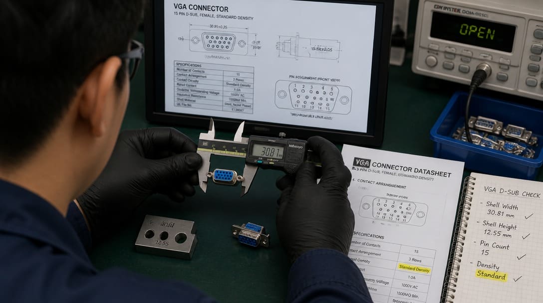
Failure Modes You Won’t See Until After Assembly
Some problems are invisible until the board is powered, the panel is closed, or the machine is shipped.
We’ve had to troubleshoot field returns where the only fault was a VGA connector with the right pin count but the wrong standoff height—the solder fillet cracked under vibration because the connector body was floating above the board instead of sitting flush against it. Loose screwlocks produce exactly the same symptom: intermittent video flicker that no software diagnostic can trace to a mechanical root cause.
Cold solder joints from mismatched plating chemistry are another classic. The joint looks acceptable under visual inspection, but thermal cycling or board flex reveals a latent open circuit. Bent pins occur when an HD15 male is forced into a DB15 female cutout—a mistake that can happen at incoming inspection when the only comparison is a photograph. Signal ghosting and interference at higher resolutions can trace back to cable-mount connectors never designed for VGA frequency ranges; internal impedance mismatches degrade the analog waveform before it reaches the monitor.
Cracked standoffs are a direct result of overtorquing screwlocks into panel holes that were tapped for a different thread pitch. The result is a connector that can no longer be secured and a mounting point that must be replaced. These failures don’t originate during design—they begin when the wrong specification lands in the kitting bin. Systematic incoming inspection, as described in quality inspection and export packaging practices, prevents these faults from ever reaching the assembly line.
Sourcing VGA Connectors: What to Ask Before You Buy
Procurement teams that treat a VGA connector as a simple commodity item risk losing assembly days to what should have been a drop-in replacement. The following questions turn a blind purchase order into a qualified procurement step.
- Provide a photo of the original connector, the PCB footprint drawing (or Gerber file), and the panel cutout dimensions with every quote request.
- Request the full specification sheet—not just the mating face drawing—to verify the plating stack, plastic material temperature rating, and solder process compatibility.
- Confirm batch traceability and consistency of performance across shipments. For legacy BOMs, lot-to-lot variation in standoff height or screwlock thread can be enough to disrupt an entire production run.
- Prefer connectors from established interconnect manufacturers—Molex, TE Connectivity, Amphenol, JST, Hirose—whose parts carry documented qualification data and are often UL Listed or Recognized for insulation and fire resistance.
- When the VGA connector is integrated into a wiring harness, extend the same scrutiny to the harness build: cutting, stripping, crimping, routing, and labeling must all match the assembly drawing. More on that process can be found at wire harness manufacturing.
Beyond VGA: Building a Sourcing Strategy for Legacy Connectors
VGA connectors are emblematic of a broader challenge. Any legacy BOM contains parts whose physical details are tribal knowledge, not written specifications. The discipline for VGA—density verification, termination matching, plating review, and process compatibility—applies to every D-sub, circular connector, and edge-board interface still in service.
A coordinated approach that connects drawing review, sample matching, and production-ready connector selection transforms a one-off firefight into a repeatable sourcing process. For buyers managing entire BOMs, this validation discipline scales to all connector types. Explore electronic connector selection and supply coordination to turn this knowledge into a systematic advantage rather than a lesson learned the hard way.
Frequently Asked Questions
What is the difference between a VGA connector and a DB15?
A VGA connector is a high-density DE-15 with three rows of five pins in an E-size shell, while a DB15 is a standard-density connector with two rows of pins in a larger B-size shell. Physically and mechanically, they are not interchangeable.
Can a DB15 connector carry a VGA signal?
No. Even if the pin count matches, the shell won’t fit the VGA receptacle and the pinout is different. The video signal may also suffer from impedance mismatches and the lack of proper ground pin locations.
What screwlock thread sizes are common on VGA connectors?
Typical threads are 4-40 UNC, M2.5, and M2.6. The exact thread depends on the equipment manufacturer’s panel design. Always verify the mating panel or cable assembly drawing before ordering.
Do PCB-mounted VGA connectors always require boardlocks?
Boardlocks are strongly recommended when the connector will experience mechanical stress from cable insertion or vibration. They prevent the connector body from lifting during soldering and provide strain relief for the signal pins. Consult the manufacturer’s application notes for your specific PCB layout.
Are VGA connectors still being manufactured and supported?
Yes. VGA remains widely used in industrial machinery, test equipment, and legacy systems. Major interconnect manufacturers continue to produce DE-15 connectors with full technical documentation and availability through authorized distribution.
Key Takeaways
- VGA connectors are DE-15 high-density, not DB15; the shell size and pin layout are definitive and non-negotiable.
- BOMs rarely specify termination method, mounting hardware, and plating stack, yet these details dictate assembly success or failure.
- Mating-face compatibility is not enough; the connector must survive the soldering process and mechanical stress of its application.
- A formal incoming inspection checklist that verifies density, gender, termination, hardware, footprint, and plating prevents line stoppages and field returns.
- When sourcing, request full datasheets, confirm batch traceability, and prefer established connector manufacturers whose parts are engineered for production.
For a comprehensive approach to connector selection and supply management, visit the electronic connectors page. For a broader overview covering all connector types and their applications, read our pillar guide on what is a connector.