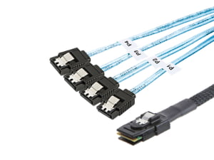
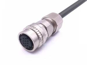
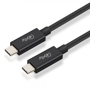
If your team is calling this a “cable assembly” but what you actually need is something that pushes, pulls, or holds tension — not something that carries voltage or signal — the distinction matters more than it looks like it should.
A mechanical cable assembly is a force-transmission assembly consisting of a wire rope or inner cable, a protective conduit, and swaged or mechanical end fittings, used to transmit push-pull or linear tensile motion between a control input and a remote actuator.
What a Mechanical Cable Assembly Is (and Why It Is Not a Wire Harness)
At first glance, a routed cable assembly and a wire harness can look similar. Both use flexible members, protective covering, termination hardware, and routing considerations. But the engineering intent is fundamentally different. A mechanical cable assembly is designed to transmit force or motion, while a wire harness is designed to route voltage, current, or data. That distinction drives material choice, termination method, testing, and packaging decisions before a drawing is ever released.
Selecting the wrong class of assembly early in a design cycle commonly leads to mismatched termination hardware, wrong bend radius assumptions, and acceptance criteria that do not reflect the actual operating environment. For example, a wire harness specification may focus on continuity and crimp pull force, while a mechanical cable assembly must also address conduit compression, swaged fitting integrity, and lost motion.
| Attribute | Mechanical Cable Assembly | Wire Harness |
|---|---|---|
| Primary function | Transmits force or motion between a control input and a remote actuator | Routes electrical power, signal, or ground between devices |
| Core components | Wire rope or inner cable, conduit, swaged end fittings, bulkhead fittings | Insulated conductors, terminals, connectors, protective sleeving, labels |
| Design inputs | Travel, load, bend radius, conduit compression, lost motion, environment | Voltage, current, signal integrity, shielding, pinouts, crimp quality |
| Failure modes | Fatigue at swaged fittings, kinked conduit, excessive lost motion, corrosion | Open circuits, intermittent continuity, insulation damage, connector mismatch |
| When specified | Throttle controls, lock releases, hoisting, remote actuation, rigging | Power distribution, data links, sensor wiring, control panels |
💡 Not sure whether your project needs force transmission, electrical routing, or both? Describe your application and our engineering team will help clarify the right assembly type before you send drawings out for quotes. Get a quick assessment →
For projects that mix both functions — such as an actuator with embedded feedback conductors or a wire harness routed alongside a mechanical control — the design team must manage two sets of requirements simultaneously. That is why the distinction belongs at the front of the specification conversation, not as a clarification after prototyping.
Core Types of Mechanical Cable Assemblies
Mechanical cable assemblies are not a single product category. The following types cover most force-transmission and motion-control applications in industrial, vehicle, and OEM equipment design.
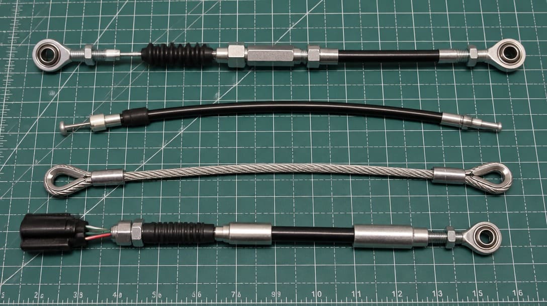
Push-pull cable transmits bidirectional force along a flexible path, making it suitable for throttles, locks, and remote actuators where the operator must both push and pull a mechanism. Its inner member must resist both compressive and tensile loads without buckling inside the conduit.
Bowden cable is a flexible mechanical cable housed inside a conduit, commonly used when force must be transmitted around curves or through confined routing. The conduit resists compression while the inner cable moves, allowing remote actuation over irregular paths.
Control cable is a broader category covering operator-initiated motion or force transmission in vehicle controls, industrial machinery, and equipment interfaces. It may overlap with push-pull or Bowden designs but is defined more by the control function than by the specific construction.
Wire rope is stranded steel cable designed primarily for tensile load, hoisting, rigging, and static support. Unlike push-pull or Bowden cables, wire rope does not always serve as an actuation path; it is often used where the assembly must carry tension rather than transmit controlled motion.
| Construction | Flexibility | Fatigue Resistance | Best Suited For |
|---|---|---|---|
| 1 × 19 | Low (Stiff) | Low | Straight-line tension, guy wires, standing rigging |
| 7 × 7 | Moderate | Moderate | General-purpose push-pull and Bowden controls |
| 7 × 19 | High | High | Frequent cycling over pulleys, tight bend radii, robotics |
Key Components: Conduit, Swaged End Fittings, and Bulkhead Interfaces
A mechanical cable assembly is only as reliable as its interface hardware and protective routing. Three components appear repeatedly in specification discussions, and each carries a specific engineering requirement.
Conduit protects and guides the inner cable. Its inner diameter, wall thickness, and material affect the minimum bend radius, abrasion resistance, and routing behavior in confined installation spaces. A conduit that is too stiff may fail to follow the intended path, while one that is too flexible can allow the inner cable to kink under load.
A swaged end fitting is a cold-formed or crimped termination that mechanically locks the cable to a fitting. The quality of the swage controls load integrity; a poorly formed swage can slip or fatigue under repeated cycling. Swaged terminations are common where the assembly must not be field-adjustable and where maximum pull strength is required.
A bulkhead fitting passes the cable assembly through a panel or enclosure wall. It must either seal the opening against moisture and dust or provide mechanical support, depending on whether the installation is indoor, outdoor, washdown, or sealed. Bulkhead sealing often becomes a design constraint when the environment is humid or the enclosure must maintain an IP-rated barrier(see our waterproof cable assembly manufacturing guide).
Lost motion is undesired free play between the control input and the actuator output. It is influenced by conduit compression, fitting tolerances, and routing geometry. Even small amounts of lost motion can degrade the feel and precision of a mechanical control, which is why conduit length, compression, and end fitting engagement must be evaluated together.
In our experience, swaged fitting quality is the single most common source of field complaints on mechanical cable assemblies — and it is also the hardest defect to catch by visual inspection alone. A swage that looks properly formed can still slip under cyclic load if the compression ratio was off during production. We pull-test every swaged termination before shipment rather than relying on visual acceptance criteria.
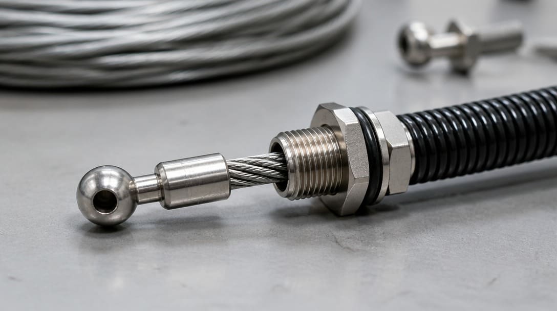
The Operating Environment Checklist That Should Precede Any Cable Assembly Specification
The most common specification error in mechanical cable assemblies is not choosing the wrong wire gauge or fitting; it is treating the environment as a secondary detail. Moisture, temperature, space, and vibration each change the material, geometry, and termination strategy. Before sending an RFQ, consolidate the actual installation conditions.
| Environmental Factor | Key Questions to Ask | Typical Design Impact |
|---|---|---|
| Moisture exposure | Sealed or humid? Washdown? Outdoor? Condensation possible? | Drives sealing, stainless or coated components, and bulkhead sealing requirements |
| Temperature range | Cold start? Continuous heat? Thermal cycling? | Affects lubricant selection, polymer softening, conduit stiffness, and seal life |
| Installation space | What is the available bend radius? Total length? Clearance at terminations? | Determines conduit flexibility, overmold envelope, and end fitting geometry |
| Vibration or mechanical stress | Continuous flexing? Shock loads? Repeated cycling? | Requires strain relief, swaged rather than clamp-type fittings, and anti-abrasion covering |
If the environment checklist reveals moisture, temperature, space, or vibration constraints, pause the RFQ and consolidate those requirements before choosing connectors, overmold geometry, or shielding. A coordinated drawing and specification review at this point avoids a redesign cycle later.
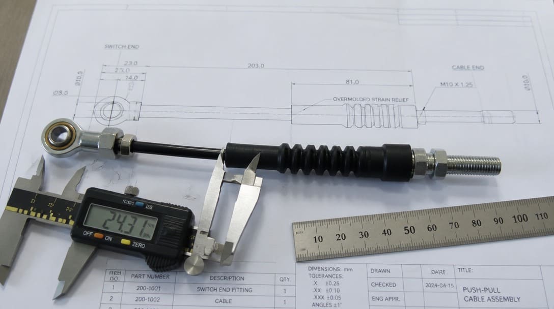
The Overmold Dimension Problem: Why Internal Layout Cannot Be an Afterthought
In assemblies that combine mechanical motion with electrical signal or power conductors, the overmold becomes a geometric constraint, not just a cosmetic or protective feature. The overmold must be thick enough to encapsulate internal components — wire terminations, shielding drain points, sensor boards, or strain relief features — but thin enough to fit the available installation space inside the product housing.
This conflict becomes acute in compact equipment. An overmold that is too thin may fail to hold internal parts or provide adequate strain relief, while one that is too thick may not fit between the enclosure wall and the PCB. When both constraints are tight, the internal layout — PCB position, grounding points, shielding arrangement, and cable exit direction — must be planned together with the overmold geometry. Attempting to adjust the overmold later often forces a board layout change or a housing tooling revision.
Shielding in Mechanical Cable Assemblies: Foil, Braid, or Combined
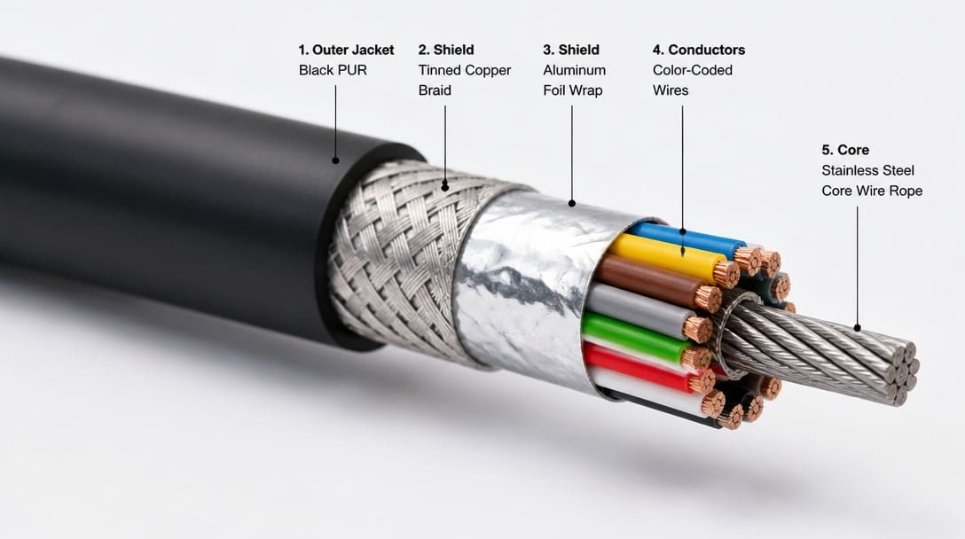
While pure force-transmission mechanical cables do not require EMI protection, shielding becomes critical in hybrid (electro-mechanical) cable assemblies containing integrated sensor/power wires, or when routed in close proximity to high-noise electrical equipment. The choice among foil, braid, or combined shielding depends on the balance between dynamic flex life, shielding effectiveness, and mechanical bend radius.
| Shielding Type | Coverage Characteristics | Flex Life and Mechanical Behavior | Typical Use |
|---|---|---|---|
| Foil | High coverage, effective against high-frequency EMI | Lighter duty under repeated flexing; can crack if continuously bent | Static or low-flex installations with strong high-frequency noise |
| Braid | Lower percentage coverage but robust grounding path | Better flex life and mechanical strength; handles repeated motion | Applications with movement, vibration, or frequent handling |
| Combined foil + braid | Broad-spectrum EMI protection with improved mechanical robustness | Highest durability but larger outer diameter; reduced flexibility may limit bend radius | High-reliability equipment with both EMI and mechanical demands |
In practice, the decision often depends on whether the assembly will flex during operation or remain static after installation. Mechanical cable assemblies with repeated cycling favor braid or combined shielding, while fixed routes inside a shielded enclosure may be adequately served by foil alone.
What to Include in a Cable Assembly Drawing to Avoid Redesign Cycles
A complete cable assembly drawing is not just a list of connector types and wire gauges. It must define the full installation context so that material choice, geometry, and acceptance criteria follow the actual application.
We regularly see mechanical cable assembly drawings that specify wire rope diameter and fitting type but leave out the minimum bend radius. The assembly gets installed in a tighter routing path than what was tested, conduit compression increases, and the lost motion ends up exceeding what the control application can tolerate — a problem that only shows up after installation, not during sample approval.
Include the following items on the drawing or in the accompanying specification:
- Operating environment conditions, including moisture, temperature, and vibration exposure
- Installation location details: inside a sealed enclosure, humid area, confined routing, or exposed outdoor area
- Fitting types, conduit length, minimum bend radius, bulkhead pass-through, and sealing requirements
- The overmold envelope and maximum allowed dimensions
- Acceptance criteria including proof load testing, minimum breaking strength (MBS), fitting pull-off force (referencing MIL-DTL-781 or OEM load specs), and electrical continuity/insulation per IPC/WHMA-A-620[1] where hybrid conductors are present.
Suppliers such as EDOM Electronics support OEM buyers with requirement review, connector matching, sample coordination, production follow-up, inspection, and export-ready packaging for custom cable assemblies and wire harnesses. That coordination is most effective when the drawing already reflects installation conditions rather than only component specifications. For export-oriented projects, aligning acceptance criteria with quality inspection and export packaging processes early prevents rework after final assembly.
From Broad Overview to Production-Ready Specification: Where This Topic Connects Next
This pillar overview establishes the foundation for a series of deeper technical comparisons. Three cluster topics extend naturally from the concepts covered here.
Mechanical vs electrical cable assembly is a foundational comparison for readers deciding between force transmission and signal or power routing. It expands the table above into detailed dual-column acceptance criteria for mixed-function systems.
Wire rope assembly explores rope construction, strand classes, and tensile load selection in more detail than the broad type description covered in this article. It is particularly relevant for hoisting, rigging, and static support applications.
Wire rope end fitting types dives deeper into swaged, swageless, threaded, clevis, and other termination options, including how each affects pull strength, field adjustability, and inspection requirements.
For project-specific drawing review, connector matching, sample coordination, and export-ready production support, continue through the custom cable assembly route when the requirements are consolidated and ready for supplier evaluation.
Frequently Asked Questions
What is the main difference between a mechanical cable assembly and a wire harness?
A mechanical cable assembly transmits force or motion through a wire rope, conduit, and swaged end fittings, while a wire harness routes electrical power or signal through insulated conductors and connectors. The distinction drives different material, termination, testing, and packaging decisions.
When is a Bowden cable preferable to a push-pull cable?
A Bowden cable is preferred when force must be transmitted around curves or through confined routing, because the conduit resists compression while the inner cable moves. A push-pull cable is more appropriate when bidirectional force must be transmitted along a relatively straight or gently curved path without conduit compression concerns.
Do all mechanical cable assemblies need shielding?
No. Shielding is only required when the assembly carries electrical conductors alongside mechanical motion or when it routes near strong electromagnetic noise sources. Purely mechanical assemblies without electrical conductors do not need foil or braid shielding.
What is lost motion, and why does it matter?
Lost motion is undesired free play between the control input and the actuator output. It is caused by conduit compression, fitting tolerances, and routing geometry. Excessive lost motion degrades control precision and can create a loose or unresponsive feel in throttles, locks, and remote actuators.
What should a cable assembly drawing include beyond connector types and wire gauge?
A complete drawing should include operating environment conditions, installation location details, fitting types, conduit length, bend radius, bulkhead pass-through, overmold envelope, and acceptance criteria such as pull force, continuity, and appearance inspection.
Key Takeaways
- A mechanical cable assembly transmits force or motion, while a wire harness routes electrical power or signal — the two should not be treated as interchangeable categories.
- Operating environment must be mapped before specifying connectors, conduit, overmold geometry, or shielding.
- Overmold dimensions are a geometric constraint: thick enough to encapsulate internals, thin enough to fit the installation space, with internal PCB and shielding layout planned together.
- Shielding choice among foil, braid, or combined depends on flex life, EMI coverage, and mechanical robustness.
- A complete drawing defines installation context and acceptance criteria, not just component types and wire gauge.
For projects that require coordinated drawing review, connector matching, sample confirmation, production follow-up, inspection, and export-ready packaging, explore custom cable assembly support.