A procurement engineer opens a BOM and sees “Molex connector” with no series number, no pitch, no part number. They think ordering any 4-pin rectangular connector will work. That decision fails at first assembly.
At a Glance
A “Molex connector” is not a universal product category. It is a brand name that has become shorthand for white rectangular pin-and-socket connectors, but Molex manufactures dozens of distinct series — each with different pin spacing, terminal retention designs, and locking geometries. The most common series found in OEM equipment include Mini-Fit Jr., Micro-Fit 3.0, KK 254, and SL. These series are not cross-compatible, and matching only the pin count and housing color regularly leads to forced insertions, intermittent contacts, and field failures. Successful sourcing requires identifying the exact series, confirming terminal type and wire range, verifying plating specifications, checking the latching mechanism, and test-fitting a sample against the original header.
What Is a Molex Connector? Clearing Up the Confusion
The phrase “Molex connector” appears on countless legacy BOMs, equipment drawings, and maintenance manuals. In practice, it tells the reader almost nothing actionable. Molex is a global interconnect manufacturer with a catalog spanning thousands of part numbers across dozens of connector families. When an OEM document from the 1990s or early 2000s lists “Molex connector” without a series designation, the engineer receiving that document today faces a significant identification challenge.
The name became genericized because Molex’s early nylon rectangular connectors — particularly the KK series introduced in the 1950s — became ubiquitous in consumer electronics, appliances, and industrial controls. Over time, any white rectangular plastic housing with a friction-lock ramp came to be called “a Molex,” regardless of the actual manufacturer or series. This verbal shorthand persists, but it masks critical differences that determine whether a connector will mate securely and carry current reliably.
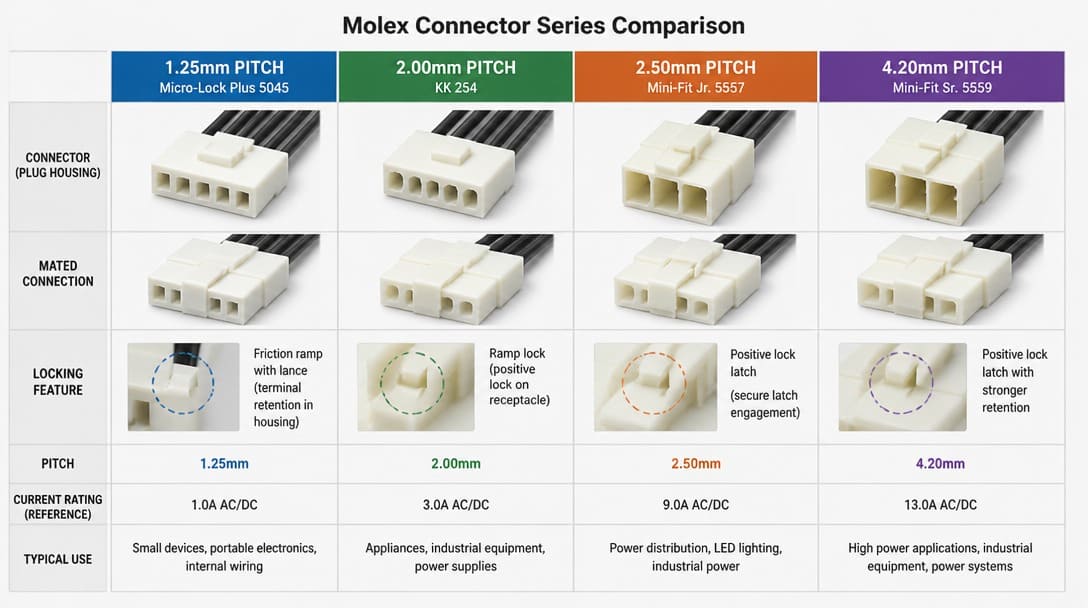
Consider the four series most frequently encountered in OEM equipment:
| Series | Pitch | Typical Application | Key Distinction |
|---|---|---|---|
| Mini-Fit Jr. | 4.2 mm | High-current power distribution, up to 9 A per circuit | Positive latch with audible click; polarized housing with multiple keying options |
| Micro-Fit 3.0 | 3.0 mm | Compact power in tight enclosures, up to 5 A per circuit | Terminal position assurance (TPA) feature; smaller footprint than Mini-Fit |
| KK 254 | 2.54 mm | Signal-level board-to-wire connections, low current | Friction-lock ramp retention; widely cloned but with subtle geometry variations |
| SL | 2.54 mm | Modular signal connections, low insertion force | IDC and crimp terminal options; terminal lance dimensions differ from KK series |
None of these series mate with one another. A KK 254 housing will not lock onto a Mini-Fit Jr. header. A Micro-Fit 3.0 terminal cannot be crimped into a Mini-Fit Jr. contact cavity. The “Molex connector” label on a BOM obscures these distinctions entirely. When an assembler attempts to force a mismatched connector, the result is often a housing that appears seated but lacks full terminal engagement — a latent failure waiting to manifest in the field.
Critical Specifications That BOMs and Drawings Often Omit
Even after the correct series is identified, a complete part number depends on parameters that many BOMs and equipment drawings simply do not specify. These omissions create procurement risk because visually identical housings can differ in ways that affect assembly yield and long-term reliability.
Termination compatibility is the most frequently overlooked variable. Crimp contacts for a given series accept a specific wire gauge range and insulation diameter. A contact designed for 18–22 AWG stranded wire will not produce a gas-tight crimp on 26 AWG conductors, regardless of how carefully the tooling is adjusted. For IDC (insulation displacement contact) variants — common in the SL series — the termination assumes a specific conductor spacing and insulation wall thickness. Using an IDC contact on wire with an oversize insulation diameter results in partial or no conductor engagement, creating an open circuit that passes a quick continuity test but fails under thermal cycling or vibration.
Plating material and thickness governs contact resistance, corrosion resistance, and soldering behavior. Selective gold plating in the contact zone provides reliable low-level signal performance over thousands of mating cycles, while tin plating offers adequate performance in static connections at lower cost. The problem arises when a replacement connector specifies tin contacts but the original header has gold-plated pins. In high-vibration environments, this mixed-plating pair accelerates fretting corrosion. Contact resistance rises gradually, and signal degradation appears months after deployment — long after the connector passed incoming inspection.
Mechanical retention method determines whether the connector stays mated under pull force, shock, and repeated handling. Friction ramps, positive latches, panel-mount ears, and board locks each impose different mechanical loads on the PCB and housing. A connector that relies solely on friction retention may back out of a panel-mounted header if the original design specified a positive latch. Procurement teams sometimes overlook this because the housing outline drawing alone does not communicate retention performance.
Regulatory blind spots compound these technical gaps. Many legacy BOMs assume rather than specify UL recognition or RoHS[1] compliance. When the replacement connector lacks UL file numbers or uses non-compliant materials, the equipment certification process stalls — a costly delay discovered only when the notified body reviews the technical file. Similarly, RoHS compliance must cover the entire interconnect system: housing, terminals, plating, and any internal lubricants.
Compatible vs. Interchangeable: Why Molex-Style Substitutes Fail
Distributors and catalog houses frequently list “Molex-style” connectors from TE Connectivity, JST, Amphenol, or Hirose as functional equivalents. The marketing term “compatible” suggests that the substitute will work, but the engineering standard is interchangeable — a far more demanding condition that requires the substitute to perform identically in the same application without modification.
The gap between compatible and interchangeable becomes apparent during mating tests. A “compatible” housing from another brand may share the same pitch and pin count, but the locking latch ramp angle can differ by a fraction of a degree. That angular difference changes the insertion force profile and the engagement depth of the latch. In practice, the connector may click into place under hand pressure on the bench, but under vibration the latch walks back, the connector partially unseats, and intermittent contact begins.
We regularly see connectors that pass visual incoming inspection but fail during assembly — the locking latch geometry on the “compatible” housing did not match the original header’s ramp angle, so the connector backs out under vibration. The assembler forces it during installation, and six months later, the field failure comes back. Terminal lance dimensions present a similar risk. A substitute terminal with a lance height that differs by 0.15 mm may not retain securely in the housing cavity, allowing the contact to back out during mating or cable routing.
Interchangeability requires mating tests performed to EIA-364 electrical connector test procedures, not just a catalog cross-reference. Pin count and pitch are necessary conditions for interchangeability, but they are never sufficient. The cost of a test-fit sample — a few housings, terminals, and an hour of technician time — is negligible compared to a line-down OEM production stop or a field recall triggered by connector failures in deployed equipment.
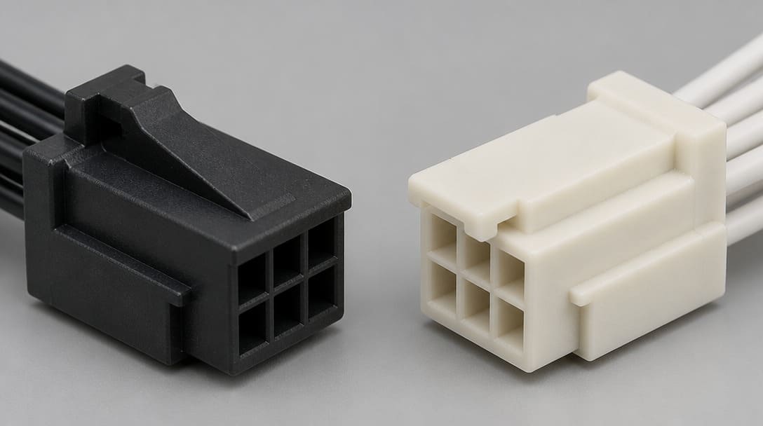
The 5-Step Connector Verification Checklist Before You Order
Before issuing a purchase order for a connector described only as “Molex” on a legacy BOM, the following five-step verification sequence reduces the probability of a mismatch to near zero. Each step addresses a specific failure mode observed in OEM procurement and harness assembly operations.
Step 1: Identify the Exact Molex Series
Measure the pitch center-to-center between adjacent pins using calipers or a pitch gauge. Count the number of rows and circuits. Compare the housing outline, keying rib location, and latch features against current Molex datasheets or a physical reference sample from the original equipment. If the equipment is accessible, photograph the mated connector pair and the header footprint. These images provide a far more reliable starting point than verbal descriptions.
Step 2: Confirm Terminal Type and Wire Range
Determine whether the original design uses crimp contacts or IDC terminals. For crimp contacts, identify the wire gauge range and insulation diameter the terminal was designed to accept. Verify that the replacement terminal matches both parameters. For IDC types, confirm the conductor spacing and insulation thickness assumed by the contact geometry. A mismatch here produces open circuits that continuity testing alone may not detect if the conductor makes marginal contact under zero mechanical load.
Step 3: Verify Plating Specification
Check the contact material, plating finish, and thickness specified for both the terminal and the mating header pin. Match the plating to the expected number of mating cycles and the environmental exposure — humidity, sulfur-bearing atmospheres, salt spray, or temperature extremes. If the original specification is unknown, a selective gold plating in the contact zone provides the broadest safety margin for signal and low-power applications.
Step 4: Check Latching Mechanism and Retention Force
Confirm whether the original design uses friction ramps, a positive locking latch, panel-mount ears, or board locks. The replacement housing must engage the header’s retention feature with the same geometry and force. If the original latch has worn or deformed over years of service, the replacement housing latch ramp may need to match the original header dimensions, not the worn condition of the field unit.
Step 5: Test-Fit a Sample with the Original Header
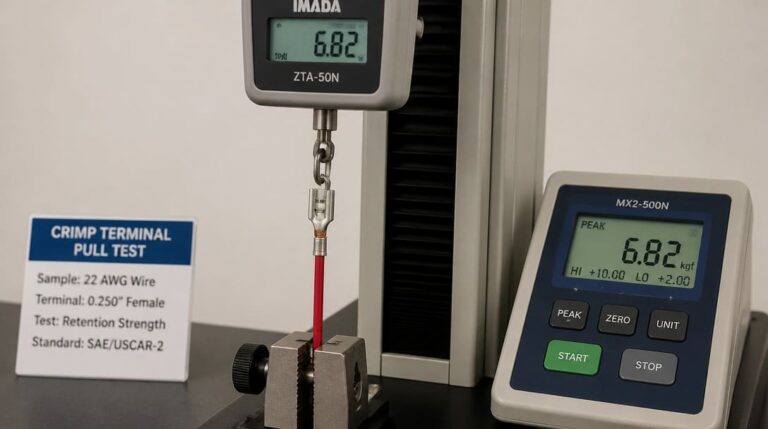
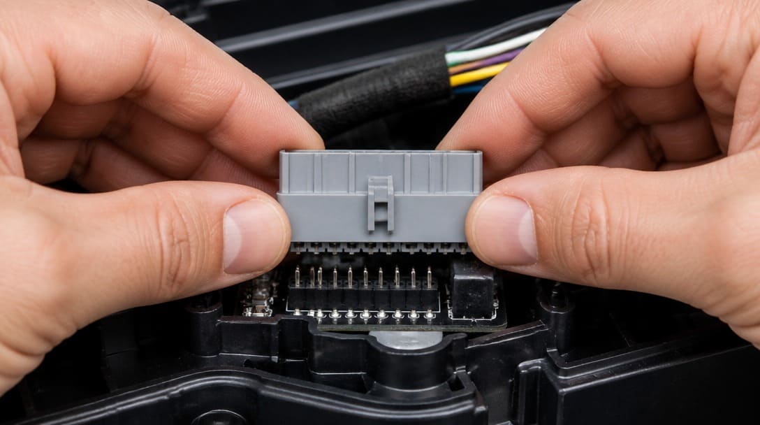
Physically mate the replacement connector with the actual header from the client’s equipment — not a catalog image, not a “should fit” assumption. Perform a pull test, inspect insertion depth, verify contact engagement, and confirm the latch seats fully. If the equipment cannot be taken offline, use a spare assembly or a known-good header sample. When a supplier cannot provide a sample, a first-article inspection with the actual header is the minimum acceptable verification before committing to a production batch.
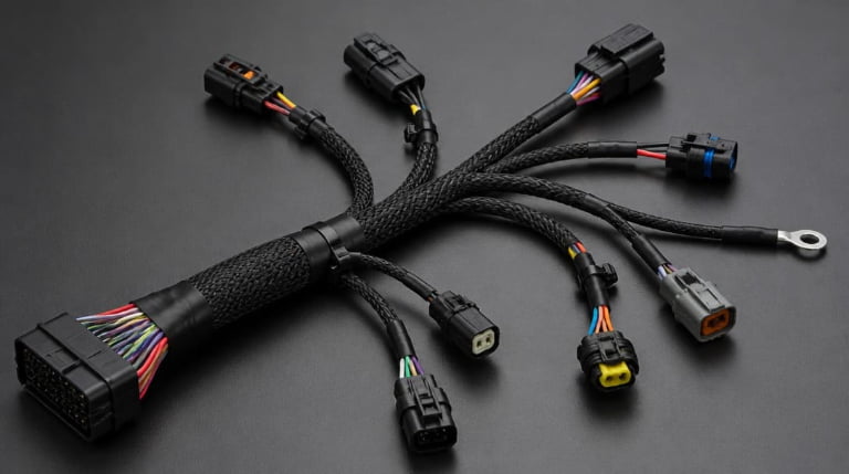
Suppliers such as EDOM Electronics support OEM buyers through this verification sequence by reviewing connector drawings, confirming series and terminal specifications, coordinating sample delivery, and performing continuity and retention checks before production begins. For custom cable assemblies and wire harnesses, this early-stage engineering review prevents the most common source of connector-related failures: a mismatch discovered only after the first batch arrives on the production floor.
Lessons from the Production Floor: Where Mistakes Compound
Connector misidentification creates consequences that ripple outward from the procurement desk to the assembly line and ultimately to the end user. The following examples are drawn from production experience and illustrate failure modes that no datasheet comparison alone would catch.
One recurring scenario involves a BOM that lists a generic “Molex 4-pin connector” for a signal harness in industrial control equipment. The procurement team sources a KK 254 housing and crimp terminals based on the pin count and the white nylon appearance. The original design, however, used an SL series IDC contact for a ribbon cable application. The insulation displacement height differed by 0.3 mm between the KK crimp terminal and the SL IDC terminal. After cable assembly, the marginal conductor engagement produced intermittent open circuits — failures that appeared only after the equipment shipped and experienced thermal cycling in the field.
Another common failure involves plating mismatch. When a tin-plated terminal is mated with a gold-plated header pin in a high-vibration environment, fretting corrosion accelerates at the contact interface. Contact resistance increases over weeks and months, not hours. The connector passes incoming continuity testing and initial equipment power-on, but signal degradation accumulates until the equipment begins to exhibit erratic behavior. Diagnosing this root cause requires disassembling the mated connector pair and inspecting the contact zone under magnification — a step rarely performed during routine troubleshooting.
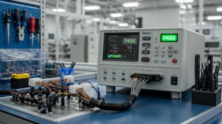
Quality checks that catch these issues before shipment include incoming terminal and housing dimensional inspection, continuity testing under mechanical stress (flexing the cable at the connector exit), cross-sectioning of crimped terminals to verify gas-tight compression, and environmental cycling of assembled harnesses to confirm that the entire interconnect system meets RoHS compliance and performs reliably across the expected temperature range. UL recognition of the connector system — housing, terminals, and wire combination — provides an additional layer of assurance that the assembly meets safety certification requirements.
For OEM buyers managing multiple legacy equipment platforms, the value of a sourcing partner that reviews drawings, specifications, and samples early in the procurement cycle is substantial. The partner maps the vague “Molex connector” description to a verifiable part number, coordinates sample confirmation, manages wire harness manufacturing with correct terminal application, and ensures quality inspection and export packaging that delivers production-ready assemblies. The alternative — ordering by appearance alone — works until it does not, and the cost of that first failure usually exceeds the cost of verification many times over.
From Legacy BOM to Reliable Supply: The Sourcing Workflow
Translating a vague BOM entry into a reliable, repeatable supply of interconnect components follows a structured workflow that mirrors the verification checklist described above. The procurement team begins with the ambiguous description and moves stepwise toward a confirmed specification.
The workflow starts with drawing analysis and sample matching. If the original equipment is accessible, the team photographs the mated connector, measures the pitch, and records any visible markings on the housing. These observations are cross-referenced against manufacturer datasheets and physical samples to narrow the identification to a specific series and terminal type. When the equipment cannot be accessed, the team relies on any available documentation — maintenance manuals, wiring diagrams, or previous purchase records — combined with conservative assumptions about the most likely series based on the application and era of manufacture.
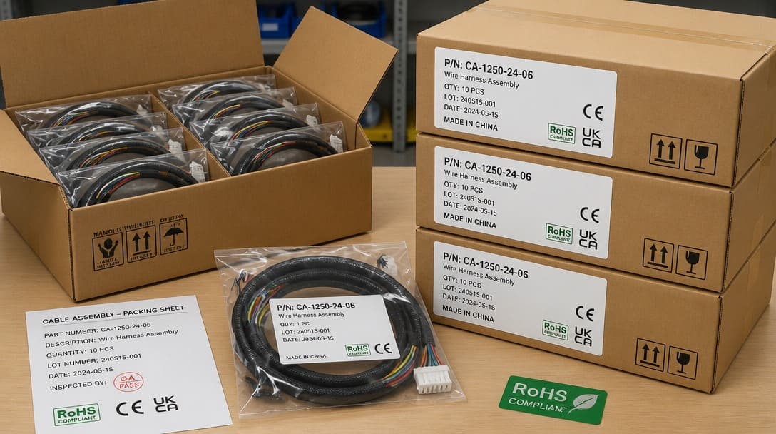
Once the series and terminal type are confirmed, the remaining parameters — wire gauge range, plating specification, and retention mechanism — are verified and documented. At this stage, a manufacturing coordination partner adds practical value by handling connector selection, terminal and cable processing, assembly routing, labeling, continuity testing, and export packaging designed for international shipping. Each carton carries part numbers, batch codes, and compliance marks that align with the buyer’s receiving procedures, distributor inventory systems, or OEM production line demand.
This disciplined approach applies equally to custom cable assembly projects where the connector is only one component of a larger interconnect system. When the specific Molex series is under control, the buyer can extend the same verification discipline to other connector families on the same BOM — JST, TE Connectivity, Hirose, Amphenol — each with its own ecosystem of pitches, terminals, and retention features.
Expanding Your Connector Expertise Beyond the Molex Name
The term “Molex connector” is a starting point for investigation, not a part number ready for ordering. Successful sourcing demands series-specific identification, parameter verification, and physical sample mating against the original equipment. The five-step checklist presented here — identify the series, confirm terminal type and wire range, verify plating, check latching mechanism, and test-fit a sample — provides a repeatable process that catches the most common failure modes before they reach the assembly line.
This detailed approach to one brand’s connector families applies with equal force to other interconnect manufacturers encountered in legacy equipment. JST connectors span multiple series with distinct pitches and terminal retention styles. TE Connectivity’s AMP line includes numerous rectangular connector families that are visually similar to Molex products but incompatible at the mating interface. Hirose and Amphenol each maintain deep catalogs with series-specific design rules. The verification discipline is the same regardless of the brand name on the housing.
For a broader foundation in connector types, termination technologies, and selection criteria that underpin all interconnect decisions, explore our electronic connector sourcing and specification resources…
Frequently Asked Questions
Why do so many BOMs just say “Molex connector” without a part number?
Legacy documentation from the 1980s through early 2000s often used “Molex” as a generic descriptor for white rectangular nylon connectors, reflecting the brand’s dominant market presence in consumer and industrial electronics. The original design engineer likely knew the exact part number, but that knowledge was lost when the documentation was simplified for purchasing or maintenance departments. Over decades of revisions, the specific series and part number were stripped away, leaving only the generic label.
Can I substitute a TE Connectivity or JST connector for a Molex part if the pitch matches?
Not without verification. While many manufacturers produce connectors in the same pitch families, the latch geometry, keying rib placement, terminal lance dimensions, and housing tolerances differ between brands. A TE Connectivity or JST housing with the same pin count and pitch as a Molex part may not lock securely onto the original Molex header. A test-fit with the actual mating header is the only reliable way to confirm interchangeability.
What is the most common mistake when ordering replacement Molex connectors?
The most common mistake is matching only the pin count and housing color, then assuming the connector will fit. This ignores the series-specific differences in pitch, terminal type, latching mechanism, and plating. A 4-pin white connector could belong to a Mini-Fit Jr., Micro-Fit 3.0, KK 254, or SL series — none of which mate with each other. The second most common mistake is overlooking the terminal’s wire gauge range, which leads to improper crimps and intermittent connections.
How can I identify a Molex connector series without any markings?
Start by measuring the pitch (center-to-center distance between adjacent pins) with calipers. Count the rows and circuits. Examine the latching mechanism — is it a friction ramp, a positive locking latch, or a panel-mount ear? Photograph the mated connector and header footprint if the equipment is accessible. Cross-reference these observations against current manufacturer datasheets or consult a supplier that offers connector identification support from physical samples or detailed images.
Does RoHS compliance matter for legacy equipment replacement connectors?
Yes. Even if the original equipment predates RoHS regulations, replacement connectors sold into markets that enforce RoHS must comply with the directive. Additionally, many OEMs now require RoHS-compliant components for all service parts regardless of the original equipment’s certification date. Non-compliant connectors can stall equipment recertification and create liability for the buyer.
Key Takeaways
- “Molex connector” is a brand name, not a part number. Legacy BOMs use this term loosely, but it conceals critical differences between series such as Mini-Fit Jr., Micro-Fit 3.0, KK 254, and SL — each with distinct pitch, terminal retention, and locking features.
- Visual similarity is dangerously misleading. Connectors that match in pin count and housing color regularly fail during assembly or in the field due to incompatible terminal lance dimensions, latch ramp angles, and plating specifications that no photograph can reveal.
- Interchangeability requires physical testing, not catalog cross-references. Substitute connectors from TE Connectivity, JST, Amphenol, or Hirose must be test-fitted against the original header to EIA-364 procedures; pin count and pitch are necessary but not sufficient conditions for reliable mating.
- A five-step verification checklist eliminates the most common failure modes. Identify the series, confirm terminal type and wire range, verify plating, check latching mechanism, and test-fit a sample before committing to a production batch.
- Early supplier engagement reduces procurement risk. Partners that review drawings, coordinate samples, and manage production follow-up catch connector mismatches before they become line-down events or field recalls.
Learn more about our electronic connector sourcing and specification support for OEM buyers.