Direct answer: Mechanical vs electrical cable assembly acceptance criteria differ in focus: mechanical criteria verify physical durability under bending, pull force, and strain(see our guide to Mechanical Cable Assemblies: Types, Components, and Design Basics), while electrical criteria verify signal and power integrity after those stresses. For OEM buyers, both columns must pass against the same IPC/WHMA-A-620[1] class; a harness that passes continuity can still fracture mechanically in the field.
Are you triaging a robotic arm harness field failure — intermittent signals, a cracked jacket, and a quality report that blames flex fatigue while the electrical sign-off shows pass? Or are you comparing two supplier quotes that disagree on whether crimp pull force or hi-pot matters more? The problem is rarely the harness itself. It is the acceptance sheet that separated mechanical integrity from electrical integrity. This article treats the two as columns of one purchase decision, structured as a sequence of go/no-go questions you can apply to a failure report or an RFQ before sample approval or production release.
What Goes Wrong in the Field When Mechanical and Electrical Sign-Off Are Separated?
The false dichotomy is common: a harness passes bench electrical tests but fractures at the overmold during flexing. The quality report blames flex fatigue, while the electrical sign-off shows continuity and hi-pot pass. The root cause is that the supplier’s acceptance sheet separated electrical continuity and dielectric testing from mechanical workmanship criteria, so neither side saw the mismatch.
Another field failure pattern is the floating shield. A braid passes crimp pull force with flying colors, but because the drain wire termination or backshell grounding is mechanically secure yet electrically open, the shield acts as an antenna and disrupts controller data lines. The shield’s pull-force result was never cross-checked against shielding effectiveness or return-path continuity. IPC/WHMA-A-620 Class 3 is the contractual remedy because it sets acceptance criteria for both mechanical and electrical workmanship in one standard. It prevents the split acceptance sheet from hiding a mismatch.
7-Step Mechanical vs Electrical Go/No-Go Acceptance Gate
Step 1: Separate the Acceptance Sheet into Two Columns — Then Force Them Back Together
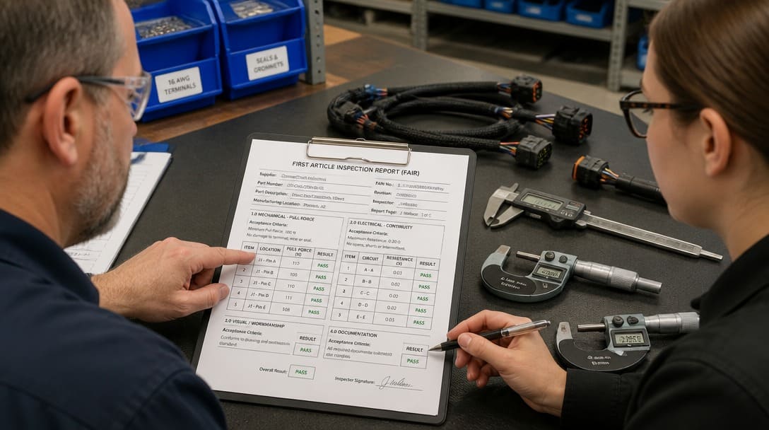
Start by auditing the supplier’s first article inspection report.For consistent quality methods, see How Manufacturers Ensure Consistent Cable Assembly Quality? Many OEM buyers find that continuity, insulation resistance, and hi-pot results appear on one page, while “mechanical workmanship” is reduced to a note or an attached photo. That split is the root cause of approving harnesses that silently fail in the field. IPC/WHMA-A-620 exists because mechanical workmanship acceptance criteria are just as critical as electrical pass/fail conditions.
- Request that the supplier list mechanical and electrical acceptance criteria side by side for every lot inspected.
- Reject any first article report that omits the specified IPC/WHMA-A-620 class or mixes criteria from different classes.
- For custom cable assembly programs, confirm that drawing review and sample confirmation include both columns before any tooling or production commitment.
Step 2: Add Mechanical Criteria That Continuity Testing Cannot Verify
Bench continuity and hi-pot sign-offs do not verify flex life. A harness can pass both while the jacket cracks at the cable-to-connector transition because the minimum bend radius was never validated, or because the strain relief did not prevent conductor movement. Mechanical criteria must appear as explicit acceptance lines, not as assumptions.
- Jacket integrity and bend radius: verify that the jacket shows no cracking, crazing, or permanent deformation after flexing at the minimum bend radius specified for the cable construction.
- Strain relief: confirm the strain relief absorbs flex stress at the overmold, backshell, or cable entry point without separation from the jacket or connector body.
- Crimp pull force: require that each terminal withstand the pull force specified by the connector manufacturer or the applicable IPC/WHMA-A-620 class without wire breakage or terminal displacement.
- Shield termination: check that braid or foil is mechanically secured to the backshell or drain wire termination without fraying, gaps, or cold-flow conditions.
IPC/WHMA-A-620 includes mechanical workmanship acceptance criteria precisely because an electrical pass alone misses field fractures at the overmold and backshell. Go/no-go rule: if the supplier’s first article report does not list mechanical and electrical results against the same acceptance class, hold approval.
Step 3: Resolve the Termination Style Trade-Off Before Releasing the Drawing
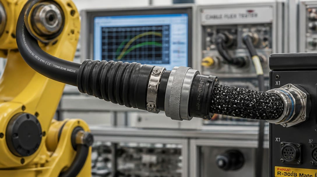
Overmolded terminations generally provide stronger strain relief, higher dielectric strength, and better IP67 sealing(see Waterproof Cable Assembly Manufacturing & Supply for OEM Buyers), but they can hide boundary cracks and reduce reworkability. Field-assembled terminations allow repair and rework, but require disciplined crimp pull force, torque, and sealing control to avoid shortened flex life. The decision should be a go/no-go purchase control, not a design preference.
| Parameter | Overmolded Termination | Field-Assembled Termination |
|---|---|---|
| Strain relief | Stronger, integrated support at cable entry | Depends on backshell grommet and crimp discipline |
| Dielectric strength | Higher, encapsulated interface reduces air gaps | Lower unless sealed with gaskets and potting |
| IP67 sealing | Readily achievable with proper mold adhesion | Achievable with gaskets, but requires torque control |
| Reworkability | Low; overmold must be cut to access terminations | High; terminals can be re-crimped or replaced |
| Crack detection | Boundary cracks can be hidden under mold | Boundary visible for inspection and repair |
Purchase-control question: for a dynamic industrial application, which termination style can pass IPC/WHMA-A-620 Class 3 flex and environmental sealing requirements simultaneously? If the answer is not documented in the drawing or FAIR, request revision before sample build.
Step 4: Move Electrical Sign-Off After Flex, Bend, and Pull Testing
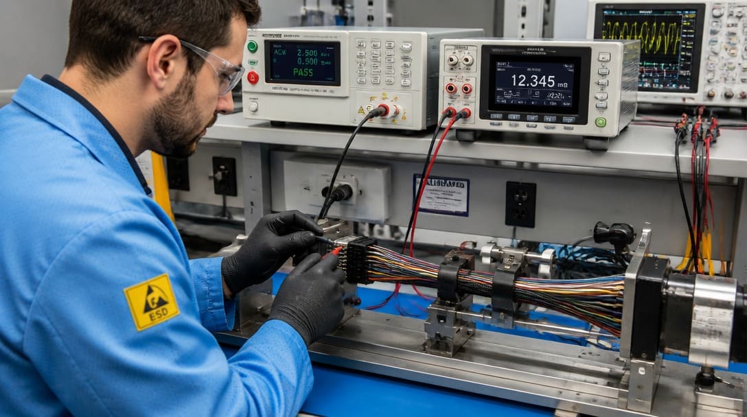
Contact resistance, insulation resistance, dielectric strength, and shielding effectiveness must be measured on the same sample after flex, bend, and pull testing — not only on a static bench sample. A pristine assembly can pass all electrical tests while the field harness develops intermittent signals because mechanical stress degraded a crimp interface or opened a shield path.
- Contact resistance: verify stability after crimp pull and flex; a change indicates a marginal crimp or wire damage inside the insulation.
- Insulation resistance: measure after mechanical conditioning to detect jacket compression or cut-through that creates leakage paths.
- Dielectric strength: test withstand voltage after flexing; a breakdown under the post-mechanical sequence reveals insulation damage that static testing misses.
- Shielding effectiveness: a shield with perfect crimp pull force can still float and act as an antenna. Shielding effectiveness depends on termination quality, grounding continuity, and the return path to the connector backshell.
Use recognized references such as IPC/WHMA-A-620 for assembly-level acceptance and UL 758[2] for wire insulation and jacket material pass/fail conditions. Do not accept unattributed numerical tolerances in a first article report. The same post-mechanical electrical verification belongs in the quality inspection and export packaging gate, so the sample that passes is structurally identical to the one shipped.
Step 5: Build the Side-by-Side Go/No-Go Checklist
Use the following decision tool as a dual-column audit. Every row must carry mechanical and electrical pass/fail conditions tied to IPC/WHMA-A-620 Class 2 or Class 3, or to recognized supplier/component specifications. The harness passes only when both columns pass for the same class and the same test sequence.
| Acceptance Area | Mechanical Criterion | Electrical Criterion | Go/No-Go Rule |
|---|---|---|---|
| Jacket and bend radius | No cracking, crazing, or permanent deformation after flex at specified minimum bend radius | Insulation resistance remains above specified limit after flex | Pass only if both columns pass for the same class |
| Strain relief | No separation from jacket or connector body; conductor movement prevented at transition | Contact resistance stable after strain relief pull test | Reject if strain relief passes visually but contact resistance shifts |
| Crimp pull force | Terminal withstands specified pull force without displacement or wire breakage | Crimp contact resistance meets connector specification after pull | Both must pass; a strong crimp with high contact resistance is a fail |
| Shield termination | Braid or foil mechanically secured to backshell without fraying or gaps | Shielding effectiveness and shield grounding continuity verified | Reject if pull force passes but shield floats or return path opens |
| Dielectric strength / hi-pot | Insulation and jacket show no cut-through, crush, or abrasion during assembly | Withstand voltage passes after mechanical conditioning, not only on static sample | Both columns must reflect the same test sequence and class |
Any row marked “unknown” is a hold. Do not release a sample or approve production while a single row lacks a documented pass from both columns.
Step 6: Set the Acceptance Class as a Contractual Requirement
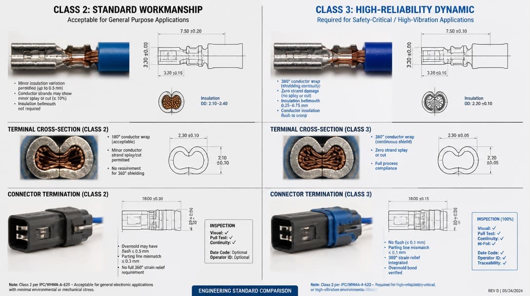
Class 2 dedicated service permits certain workmanship conditions that may be acceptable for static equipment but shorten life in continuous motion. Class 3 assumes harsh, continuous flex or motion and sets tighter mechanical and electrical acceptance criteria for robotic arm harnesses. The class is not a footnote; it is a contractual purchase control.
Go/no-go: require the drawing, first article, and production traveler to state the class explicitly. Reject class ambiguity or mixed-class acceptance. For a robotic arm harness, the default must be Class 3 unless a documented engineering deviation justifies otherwise.
Step 7: Execute the Go/No-Go Gate on the First Article Inspection Report
Take the field failure report or the two supplier quotes and mark each row of the decision tool as pass, fail, or unknown. That exercise exposes missing data faster than any narrative explanation. Then demand that the supplier’s first article inspection report show mechanical and electrical results side by side against the same IPC/WHMA-A-620 class — not in separate annexes, not with ambiguous class numbers, and not with unattributed tolerances.
- If the FAIR separates electrical and mechanical sign-off, reject it and request revision.
- If the class is omitted or changes between jacket, bend radius, shield, and hi-pot sections, reject it.
- If any row is “unknown,” put sample approval and production release on hold until the supplier provides verified pass/fail for both columns.
- Use the matrix as the final gate before approving the sample for shipment preparation and export packaging.
For OEM buyers who need a supplier that structures acceptance reports in this dual-column format, a partner with disciplined wire harness manufacturing and inspection workflows can reduce the chance of approving a harness that passes one side and silently fails the other. Suppliers such as EDOM Electronics support OEM buyers with requirement review, connector matching, sample coordination, production follow-up, inspection, and export-ready packaging for custom cable assemblies and wire harnesses. That support matters most when the acceptance document itself must be rebuilt before the next prototype order.
How Does IPC/WHMA-A-620 Class 2 vs Class 3 Change the Acceptance Decision for a Dynamic Industrial Application?
| Parameter | Class 2 | Class 3 |
|---|---|---|
| Intended service | Dedicated service with limited motion and extended downtime | Harsh, continuous flex or motion where failure is not tolerable |
| Bend radius validation | Less stringent; some workmanship anomalies may be acceptable | Tighter minimum radius and stricter post-flex acceptance |
| Crimp inspection | Sample-based with standard criteria | More comprehensive with tighter pull force and visual requirements |
| Documentation | Standard inspection records | Full traceability and dual-column FAIR expected |
Frequently Asked Questions
What is the difference between mechanical and electrical cable assembly acceptance?
Mechanical acceptance verifies physical durability under bending, pull force, and strain relief conditions. Electrical acceptance verifies contact resistance, insulation resistance, dielectric strength, and shielding effectiveness after those mechanical stresses. Both must pass against the same IPC/WHMA-A-620 class for the harness to be approved.
Can a cable assembly pass electrical tests but still fail in the field?
Yes. A harness can pass bench continuity and hi-pot while the jacket cracks at the overmold during flexing, or while a floating shield with perfect crimp pull force acts as an antenna. These failures occur because the electrical sign-off was separated from mechanical workmanship validation.
What IPC/WHMA-A-620 class should a robotic arm harness meet?
For dynamic industrial applications with continuous motion, harsh environments, or where failure interrupts production, Class 3 is the appropriate default. Class 2 may be accepted only with a documented engineering deviation, but the class must appear on the drawing and first article report without ambiguity.
Should shielding effectiveness be tested before or after flex testing?
Shielding effectiveness should be tested after flex, bend, and pull conditioning on the same sample used for mechanical acceptance. A shield can be mechanically secure yet electrically open; the return path and grounding continuity must be verified under post-mechanical conditions.
How can an OEM buyer verify a supplier separates mechanical and electrical sign-off correctly?
Request a first article inspection report that shows mechanical and electrical results side by side, row by row, against the same IPC/WHMA-A-620 class. Reject reports that separate the two columns, omit the class, or use unattributed numerical tolerances.
Key Takeaways
- Mechanical integrity and electrical integrity are two columns of one acceptance decision; a cable assembly must pass both against the same IPC/WHMA-A-620 class.
- Static bench electrical sign-off is not proof of field durability. Contact resistance, insulation resistance, dielectric strength, and shielding effectiveness must be measured after flex, bend, and pull testing.
- Use the dual-column go/no-go checklist to audit any supplier FAIR or field failure report. Any row marked “unknown” is a hold.
- For dynamic industrial applications such as robotic arm harnesses, explicitly specify IPC/WHMA-A-620 Class 3 and reject mixed-class acceptance.
- A floating shield with perfect crimp pull force can still act as an antenna. Verify shield grounding and shielding effectiveness as electrical criteria, not just mechanical termination.
For buyers evaluating new harness suppliers or re-qualifying an existing one, explore custom wire harness manufacturing support that includes drawing review, dual-column first article reports, crimp verification, and export packaging coordination.