Bird caging in wire harnesses, as covered in our What Is a Wiring Harness? Key Components, Functions & Applications guide, is a defect condition in which the individual strands of a stranded conductor separate and flare outward near a termination, backshell, or insulation support, typically caused by strip-length drift, insufficient insulation support, damaged termination tooling, or improper installation loads, and it must be evaluated against IPC/WHMA-A-620[1] acceptance criteria before lot disposition.
Bird Caging Field Failures: Does One of These Two Scenarios Sound Familiar?
One scenario begins with a field return: a harness that passed final inspection shows frayed strands at the backshell exit after only weeks of installed service. The written inspection report says visual check passed. The second scenario begins at incoming inspection: a technician flags a small flare at the insulation grip, but the lot is accepted after a bench-level appearance review because the exposed strands are not grossly separated and continuity is intact.
Both situations point to a problem that visual acceptance can miss. Separated strands often sit just beyond the insulation grip, in a zone where bench inspection was not required to measure or magnify. By the time a failure photograph exists, the harness has already drifted from print conditions or tooling control. The diagnostic question is not whether the harness “looks bad” but which root cause the strand pattern points to—and what to decide next.
Strip-Length Drift: The First Check When Strands Flare Evenly
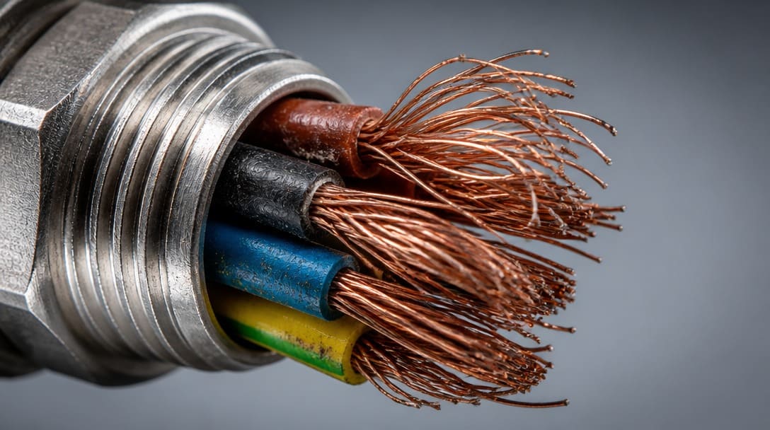
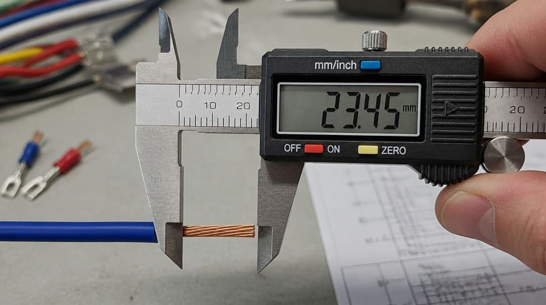
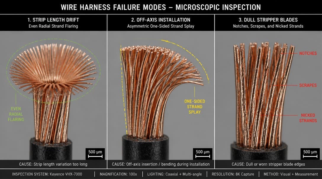
When the flared strands distribute evenly around the conductor circumference, the first measurable suspect is strip-length drift. A strip operation that runs long—sometimes by only a fraction of a millimeter beyond the allowed window—exposes the twisted lay length of the stranded conductor outside the insulation grip. The available mechanical margin shrinks as the strands become smaller: for a given strip error, finer strands on a smaller AWG conductor have less resistance to splaying than heavier strands on a larger AWG conductor.
Compare the measured strip length against the drawing and the applicable acceptance window. If first-article strip length was not recorded, an acceptance lot can pass bench continuity while carrying a latent backshell-exit defect. Bench continuity only confirms electrical path; it does not verify that the insulation support still grips the intended strand bundle at the correct position.
Decision: When strip length falls outside the drawing or the relevant IPC/WHMA-A-620 acceptance condition, reject or contain the lot and request correction. Sorting the existing inventory may recover some units, but without a corrected stripping setup, the next lot will repeat the same flare. The response is process correction, not a simple sort.
Insulation-Support Geometry: Why a Harness Passes Bench Checks But Fails in Service
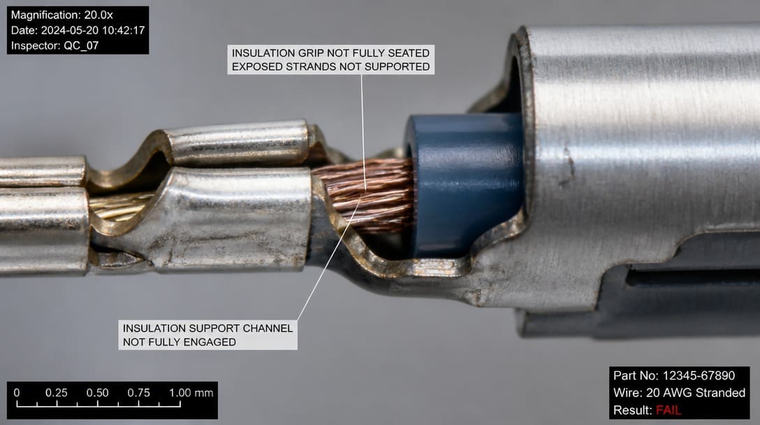
The backshell exit is a stress concentration. Insulation support must extend into the closure area so that strands are not unsupported at the transition from bundle to termination. Marginal support geometry may look acceptable on a static bench because the strands hold their position under zero mechanical load, but the same transition can turn into intermittent strand movement under vibration and bundle loading once installed.
For aerospace or defense applications using thin-wall constructions such as those described by MIL-W-22759(see our OEM wiring harness selection guide), thickness margins around the insulation grip are tighter. High-strand-count conductors also leave less room for support error. Evaluate insulation support position with magnification, checking whether the insulation fully enters the closure area and whether any strand group sits unsupported at the exit plane.
Decision: When support geometry is marginal, request supplier corrective action rather than sorting. Sorting only catches the current visible condition; it does not move the insulation support back to the print location on the next production run.
Termination Tooling Condition: Notched, Scraped, or Cut Strands Point to Process Drift
Notched or scraped strands at the strip or crimp area indicate dull blades, misaligned stripping dies, or excessive grip pressure rather than a wire material issue. The harness can still pass continuity testing after tooling damage because the conductor remains electrically intact, but each notch becomes a fatigue point. Under repeated flex or vibration, that local damage propagates into a broken strand or an open circuit.
Use magnification on sample strip ends and crimp areas. Compare notch location and frequency to known tooling wear patterns before dispositioning an incoming lot. A single isolated notch may be random, but repeated notches at the same radial position across multiple samples point to a dull stripping blade or a worn die. The AWG of the conductor matters here: finer strands tolerate less mechanical abuse before visible damage appears.
Decision: Tooling-related damage is evidence of process drift. The correct response is corrective action on tool maintenance and replacement intervals, not a sort-only disposition. Sorting may quarantine the visibly damaged units, but it cannot fix the dull blade that produced them.
Bird-Caging Root-Cause Decision Table: Match the Strand Pattern to the Likely Cause
Use the observed strand pattern as a triage tool before rejecting or sorting the lot. The table below maps the most common physical evidence to the likely root cause and the next action the quality engineer should take.
| Observed Strand Pattern | Likely Cause | Next Action |
|---|---|---|
| Even flare around the conductor circumference | Strip-length drift exposing the twisted lay length beyond the insulation grip | Measure strip length against the drawing and AWG-specific window; reject or contain if outside acceptance criteria |
| One-sided flare at the backshell exit | Insulation-support geometry or asymmetric bundle loading | Inspect support engagement into the closure area and check installed routing for off-axis loads |
| Notched, scraped, or cut strands at strip or crimp area | Termination tooling condition—dull blades, misaligned stripping dies, or excessive grip pressure | Inspect stripper blades, dies, and grip pressure; request tool maintenance corrective action |
This pattern-based triage does not replace full dimensional inspection, but it focuses the next measurement and containment decision where the evidence is strongest.
IPC/WHMA-A-620 Pass/Fail: When Birdcaged Strands Are a Defect, Not a Cosmetic Note
Separated or birdcaged strands are a defect condition under IPC/WHMA-A-620, the acceptance standard for cable and wire harness assemblies. They are not an appearance note or an acceptable variation. The standard defines three workmanship classes with increasing inspection and documentation rigor; the applicable class determines the exact acceptance threshold, but none of the classes permit unrestricted strand separation at a termination or backshell exit.
The practical disposition follows the confirmed condition. Reject the lot when a separable condition is confirmed on inspected units and the drawing or standard requires rejection. Sort and reinspect only when the defect is isolated and the acceptance criteria allow verification of the remaining units against an expanded inspection plan. If the strand pattern points to strip-length drift, support geometry, or tooling wear, sorting without corrective action will not prevent recurrence in the next lot.
IPC/WHMA-A-620 Quick Class-Disposition Boundary:
- Class 1 (General Electronic Products): Acceptable if strand separation does not exceed wire OD, strands remain undamaged, and electrical clearance is maintained.
- Class 2 (Dedicated Service Electronic Products): Defect if separation violates minimum electrical clearance, breaks the outer profile boundary, or limits proper insulation crimp capture.
- Class 3 (High Performance/Harsh Environment): Defect if any wire strand separation extends outside the original lay pattern or beyond the terminal insulation support boundary prior to/after installation.
When a written inspection report says visual check passed but the failure photo shows strand separation outside the insulation grip, recheck the backshell exit with magnification and document the mismatch between the report and the physical evidence. A supplier-facing corrective action request should reference the standard by name and describe the observed condition, not quote an internal opinion. For buyers managing incoming QC at the warehouse level, an expanded inspection plan and export packaging verification are part of a closed-loop response; quality inspection and export packaging support can help standardize that inspection boundary.
What Goes Wrong After a Visually Passed Harness: Vibration, Bundle Settling, and Minimum Bend Radius
Vibration at the backshell exit turns marginal insulation support into intermittent opens. Strands can fatigue without gross damage at incoming inspection because the damage accumulates only under dynamic load. After installation, bundle settling changes the mechanical loads at the exit: a strip length that passed bench checks can fail once the harness is routed, secured, and subjected to its own weight plus adjacent bundle movement.
Evaluate the minimum bend radius—the smallest radius a wire can be bent without damage—at the exit point. If the installed bend is below the wire or print guidance, stress concentrates at the strand-to-support boundary. UL 758, the safety standard for Appliance Wiring Material covering insulated wire and cable styles, provides a reference for insulation toughness and intended service conditions, but it does not override the specific pass/fail criteria of IPC/WHMA-A-620. Visual smoothness alone is not an acceptance test.
For custom cable assemblies and OEM harnesses subjected to similar exit loads, the same failure mode appears across product families. Field returns with fraying require checking installation routing and support alongside supplier lot measurements. Share photos, strip-length data, and installed routing angles with the supplier before requesting rework. A supplier that supports custom cable assembly projects can often provide retained samples and measurement records that distinguish a lot-specific error from a systemic process drift.
Next Decision: Reject, Sort, or Require Supplier Corrective Action
Strip-length drift, insulation-support geometry, and termination tooling condition are the leading indicators for backshell-exit strand fraying. The evidence-based decision sequence is straightforward:
- Quarantine suspect inventory immediately.
- Photograph the strand pattern at the exit zone, not just the overall harness.
- Measure strip length on a sample set and compare each measurement to the drawing and the applicable IPC/WHMA-A-620 acceptance condition.
- If tooling damage is visible, inspect stripping blades and crimp dies for wear, misalignment, or incorrect grip pressure.
- Request supplier corrective action with the photographic evidence and measurement data attached.
If the incoming report says visual passed but the photo shows damage outside the normal inspection point, expand the inspection plan to include the backshell exit zone as a named inspection requirement, not an implied afterthought. Use retained samples and past lot data to determine whether the condition is lot-specific or systemic across recent shipments. A lot-specific defect may be sorted and reinspected; systemic drift requires process correction before the next batch is accepted.
Suppliers such as EDOM Electronics support OEM buyers with requirement review, connector matching, sample coordination, production follow-up, inspection, and export-ready packaging for custom cable assemblies and wire harnesses. When a bird-caging failure requires corrective action, that kind of documented production record and packaging control helps separate a one-off deviation from a recurring process problem.
Frequently Asked Questions
What is bird caging in wire harnesses?
Bird caging is a defect condition in which the individual strands of a stranded conductor separate and flare outward near a termination, backshell, or insulation support instead of remaining tightly twisted in the intended lay. It must be evaluated against the acceptance criteria of IPC/WHMA-A-620.
Is bird caging always a reject under IPC/WHMA-A-620?
No, not automatically. IPC/WHMA-A-620 defines three workmanship classes with different acceptance thresholds. A separable birdcage condition at a termination or backshell exit is typically a defect, but the exact disposition depends on the class, the drawing, and whether the condition is isolated or systemic.
How can incoming inspection detect bird caging that visual checks miss?
Expand the inspection plan to include the backshell exit zone with magnification. Measure strip length against the drawing and AWG-specific window, and inspect strand condition at the strip and crimp areas. Bench continuity alone will not detect latent bird-caging because the conductor remains electrically intact until fatigue begins.
What causes bird caging after a harness has been installed?
Vibration at the backshell exit, bundle settling, and an installed bend below the minimum bend radius can all turn a marginal insulation support into intermittent strand movement. The original strip length or support geometry may have been acceptable on a static bench but fails under service loads.
Should a bird-caged lot be sorted or rejected?
Sorting only makes sense when the defect is isolated and the acceptance criteria allow verification of the remaining units. If the strand pattern points to strip-length drift, insulation-support geometry, or tooling wear, the root cause must be corrected at the supplier process level before the next lot is accepted.
Key Takeaways
- Bird caging is a defect condition under IPC/WHMA-A-620, not a cosmetic note; it requires a go/no-go disposition based on strand separation at the termination or backshell exit.
- Even flare around the conductor circumference points first to strip-length drift; measure strip length against the drawing and the AWG-specific window before rejecting or sorting.
- One-sided flare at the backshell exit usually indicates insulation-support geometry or asymmetric bundle loading, not a wire material fault.
- Notched, scraped, or cut strands are tooling-related process drift; the corrective action is tool maintenance, not a sort-only disposition.
- A visual pass on the bench does not rule out field failure under vibration, bundle settling, or a bend below the minimum bend radius. Expand the inspection plan to include the backshell exit zone.
For OEM buyers and quality teams managing wire harness production across multiple lots, explore wire harness manufacturing and inspection support options that include requirement review and documented production records.