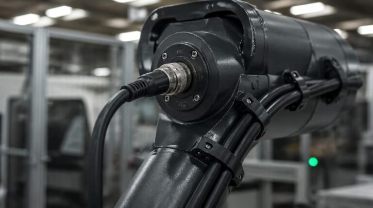
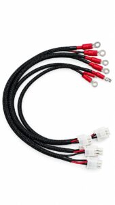
Direct answer: A robotics cable assembly is a motion-rated interconnect system that combines extra-flexible stranding, compression-resistant insulation, and a motion-matched shield termination with a jacket engineered for dynamic bending, torsion, or combined six-axis movement, used to maintain signal and power continuity across moving robot joints.
Your six-axis prototype passed continuity and initial bend checks. Then it failed the two-million-cycle bend-radius endurance test with intermittent signal loss at a high-flex joint. Or the field units pass a bench check but drop out at one arm angle. If either sounds familiar, the problem is not an ordinary open circuit. Flex life is not a wire-gauge problem. It is a balance among stranding, insulation compression, shield termination, and jacket material.
When a Six-Axis Prototype Fails at Two Million Cycles
The failure usually appears after the first endurance run. A six-axis arm may pass static continuity checks and initial bend validation, then lose signal at the joint with the tightest dynamic bend radius. The common field pattern is intermittent dropout at one repeatable arm position, not a dead conductor that a bench meter can identify. That points to a motion-mode failure: conductor fatigue under intact insulation, shield braid fracture, or a stiff overmold concentrating flex stress.
The engineer’s first job is therefore not to increase the wire gauge. It is to classify the exact motion the cable must survive, then specify conductor, insulation, shield, and termination in that order(see Rugged Robotics Cable Assemblies: Key Design Considerations). A larger general-purpose conductor can fail earlier than a smaller motion-rated conductor if the stranding and insulation were not selected for the specific movement.
Lock the Motion Mode Before Specifying Anything
Rolling bend, torsion, continuous flex, and combined six-axis movement are separate specifications. A drag chain cable that survives rolling bend in an energy chain is not automatically a torsion cable for a robot wrist. Each motion mode creates a different stress distribution across the conductor bundle and jacket.
Rolling bend in an energy chain requires a continuous-flex cable or drag chain cable rated for the smallest dynamic bend radius in the installation. The cable must tolerate repeated curvature without the conductors migrating through the insulation or the shield opening at the bend apex.
Torsion in a robot joint requires a torsion cable with special lay length, center fillers to control conductor positioning, and a jacket formulated to twist without core corkscrewing. In a six-axis arm, the worst-case joint usually combines bending and twisting. Specify the cable for that worst-case motion mode, not the average motion across the arm.
Conductor Stranding and Insulation: The Real Flex Life Limiters
Conductor construction controls fatigue life. Extra-flexible stranding uses many fine strands that distribute bending stress across a larger total surface area and delay the growth of fatigue fractures. Coarse-stranded conductors concentrate strain in fewer individual wires and fail earlier under repeated motion, even when the overall cross-section has enough ampacity.
Insulation selection is compression management. Under a tight bend radius, the inner conductors compress against each other and the insulation cold-flows. Materials with low compression set and superior fatigue recovery, such as dynamic-grade TPE, polypropylene (PP), and abrasion-resistant PUR (polyurethane), resist cold-flow deformation significantly better than conventional PVC compounds under continuous flexure. A thinner low-compression-set insulation can protect the conductor core more effectively than a thicker rigid insulation that develops cracks and shorts under dynamic load.
In rolling bend applications, fine-stranded conductors paired with TPE or PP insulation commonly outlast coarse-stranded heavy PVC-insulated conductors of the same ampacity by a multiple, not a percentage. The engineering rule is to specify by motion stress first and ampacity second. Where the product is bound for the European market, specify RoHS-compliant insulation and jacketing compounds as part of the material record.
Shield Termination and Grounding: Where Continuous Flex Cables Fail Silently
Shield braid fatigue in torsion frequently passes continuity checks while partially intact. A portion of the braid strands fractures, but enough remain in contact for a DC meter to read zero ohms. The cable still loses shielding effectiveness and intermittent EMI-induced signal dropouts appear. For continuous-flex cable in combined motion, specify a shield construction with a controlled lay angle matched to the torsional direction, not a generic spiral or random braid.
Grounding must be decided before termination. Single-end grounding can reduce low-frequency ground loops, but high-frequency noise may require grounding at both ends with proper potential equalization. Document the choice in the drawing notes and apply it consistently. If the harness passes through a moving joint, separate the shield termination point from the maximum flex zone so the mechanical flexure does not work the drain wire loose.
At the connector, terminate shields with low-resistance drain or 360-degree contacts at the connector body. A long pigtail creates a high-inductance path and a moving failure point. The shield should leave the flex zone and enter the connector backshell without changing its electrical geometry.
Go/No-Go Selection Table for Robotics Flex Cables
The table below summarizes the go/no-go criteria for the three dominant motion modes in robotics. Use it before ordering another endurance test.
| Motion mode / dominant failure mode | Conductor construction | Insulation system | Shield termination | Required test evidence |
|---|---|---|---|---|
| Rolling bend in a drag chain | Class 6 extra-fine stranding (0.05 mm to 0.08 mm copper wire diameter); no coarse Class 2/5 conductors | Low compression set TPE or PP insulation; dynamic bend radius rated to ≤ 7.5× outer diameter (OD) | 360-degree shield contact via clamping backshell at connector body; drain wire anchored outside maximum flex zone | Dynamic drag-chain cycling (minimum 5M to 10M cycles at target radius) with real-time continuous electrical microsecond-discontinuity monitoring |
| Torsion in a wrist joint | Special lay length with center fillers; no corkscrew-prone construction | Twist-tolerant jacket compound matched to core lay | Shield braid lay angle matched to torsion direction; single-ended grounding documented for low-frequency analog, both ends with equalization for high-frequency noise | Torsion endurance cycling at specified ± angle, followed by visual strand-count and insulation crack inspection |
| Combined six-axis movement | Fine stranded conductor with controlled lay for bending plus twisting | Compression-resistant insulation selected for worst-case motion mode | 360-degree shield termination at connector body, with flex zone separation from shield termination point | Combined motion endurance test, no discontinuity longer than defined threshold during test, then post-test strip inspection |
Termination and Overmold Decisions Come Last
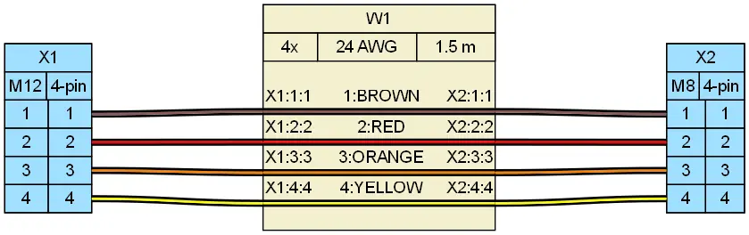
Circular connector interfaces such as the 12 mm threaded M12 connector and the smaller 8 mm threaded M8 connector are common in robot sensor and end-effector applications because they provide compact, locking, IP67-rated connections. IP67 protects against dust and temporary immersion, but an IP67 overmold that creates a stiff transition can concentrate flex stress at the cable-to-connector junction and fail before the cable body.
Select the M12 or M8 connector after the conductor and shield choices are locked. The connector must match the harness’s dynamic section, not just the panel cutout or sensor pinout. For a torsion joint, orient the circular connector so the cable’s natural twist direction does not unscrew the threaded coupling or fatigue the termination at the backshell.
The overmold strain relief should use a progressive stiffness profile from cable jacket to connector body. Avoid heatshrink or rigid potting at the exit point in high-flex zones. A flexible tapered strain relief distributes the transition over a longer length and reduces the stress concentration that causes premature jacket cracking.
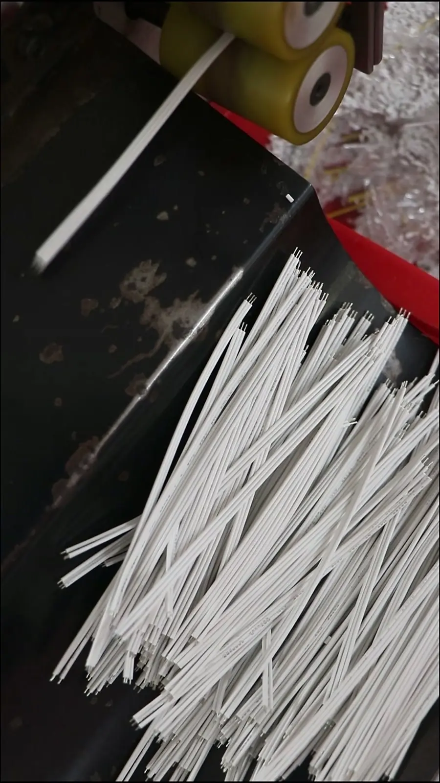
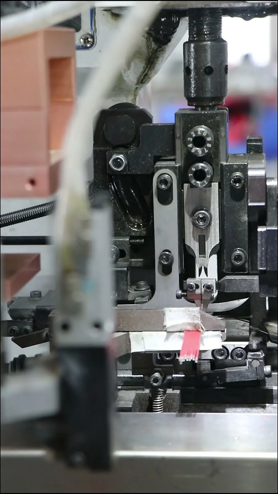
When the drawing moves to production, a documented wire harness manufacturing process should control cutting, stripping, and crimp termination at the dynamic section.
Set a Bend-Cycle Protocol: IPC/WHMA-A-620 Class 3 Is the Floor, Not the Finish
IPC/WHMA-A-620 defines three workmanship acceptance classes for cable and wire harness assemblies, with Class 3 requiring the most stringent inspection and documentation. Specifying Class 3 reduces strand damage, insulation gaps, and improper crimp strain relief during production. But passing visual acceptance criteria does not guarantee dynamic endurance. A harness can look perfect on the bench and still fail after two million flex cycles.
A bend-cycle test protocol should be defined before sign-off. The protocol needs a stroke length, speed, bend radius multiplier, required number of cycles, and an electrical pass/fail threshold — for example, no discontinuity longer than one microsecond during test. After the mechanical cycling, strip the jacket over the flex zone and count broken strands, insulation cracks, and shield deformation against go/no-go limits. Visual inspection alone is not enough. Crimp terminations in the dynamic section should also be verified to solderless connection standards such as IEC 60352, while soldered terminations follow IPC J-STD-001 methods and acceptance criteria.
Require test evidence from the cable assembly supplier or a certified lab before production release. For OEM buyers, suppliers such as EDOM Electronics support requirement review, connector matching, sample coordination, production follow-up, inspection, and export-ready packaging for custom cable assemblies and wire harnesses. For production release, the quality inspection and export packaging process should include bend-cycle evidence, connector push-pull checks, and export packout that protects overmold strain reliefs from crush damage.
What Goes Wrong in the Field
Field failures in robotics cable assemblies often pass bench continuity checks. The first pattern is fractured strands under intact insulation. The conductor still touches enough to show continuity, but resistance rises and signal dropouts appear only at one arm position. A standard multimeter cannot detect the partial fracture.
The second pattern is shield braid fatigue in torsion. The shield may appear continuous but individual strands are broken, reducing shielding effectiveness and allowing intermittent EMI-induced signal loss. This is why the shield lay angle and termination style must match the torsion cable specification.
The third pattern is a stiff overmold strain relief becoming a flex stress concentrator. The transition point fails first, even though the cable body and connector pass bench inspection. And the root cause of many late-cycle endurance failures remains the same: misclassifying the motion mode at the drawing stage.
Frequently Asked Questions
What is the difference between a drag chain cable and a torsion cable?
A drag chain cable is designed for rolling bend in an energy chain, where the cable bends around a defined dynamic bend radius as the chain moves. A torsion cable is designed for twisting around its own axis, typically in a robot wrist joint, and uses a special lay length, center fillers, and a twist-tolerant jacket to prevent corkscrewing.
When should an M12 connector be used instead of an M8 connector?
M12 connectors have a 12 mm threaded coupling and are commonly used for industrial Ethernet, power, and multi-signal connections in robotics. M8 connectors have an 8 mm threaded coupling and are better suited to compact sensor and actuator connections where board or panel space is limited. The choice depends on pin count, current, and available mounting space, not just the panel cutout.
Does Class 3 to IPC/WHMA-A-620 guarantee flex life?
No. IPC/WHMA-A-620 Class 3 defines stricter workmanship acceptance criteria that reduce strand damage and insulation gaps during assembly, but it does not measure dynamic endurance. A bend-cycle test protocol with defined cycles, bend radius, and electrical pass/fail thresholds is required to validate flex life.
Why do some robot cables pass continuity checks but fail in the field?
Fractured conductor strands, partial shield braid fatigue, and stiff overmold transitions can all pass static continuity checks because enough conductive material remains in contact. Under motion, resistance changes and shielding effectiveness drops, producing intermittent signal loss only at specific arm angles.
How should OEM buyers evaluate a custom robotics cable assembly supplier?
Buyers should review how the supplier handles drawing review, connector matching, sample confirmation, bend-cycle test evidence, production follow-up, inspection, and export packaging. For example, EDOM Electronics supports OEM buyers with drawing review, connector matching, sample coordination, production follow-up, inspection, and export-ready packaging for custom cable assemblies and wire harnesses.
Key Takeaways
- Classify the motion mode first — rolling bend, torsion, continuous flex, or combined six-axis — because a drag chain cable is not automatically a torsion cable.
- Select extra-flex fine stranding and low-compression-set insulation such as TPE or select PVC compounds; do not specify by ampacity alone.
- Match shield lay angle, grounding scheme, and 360-degree termination to the motion mode, and keep the termination point out of the maximum flex zone.
- Choose M12/M8 circular connectors and overmold strain relief after conductor and shield decisions; a stiff IP67 overmold can become a flex stress concentrator.
- Define a bend-cycle endurance protocol with pass/fail electrical thresholds and post-test strand inspection, because IPC/WHMA-A-620 Class 3 workmanship is not a flex-life guarantee.
For OEM robotics programs facing motion fatigue or intermittent joint dropouts, explore EDOM Electronics’ custom cable assembly solutions. We provide 24-hour DFM drawing reviews, motion-mode validation (torsion vs. drag-chain), and rapid functional prototyping delivered in 3–5 business days to accelerate your pilot runs.