Direct answer: Partial discharge (PD) testing in cables is a specialized factory acceptance measurement—complementing routine cable tester quality inspection—that detects localized electrical discharges inside insulation voids, gaps, or contamination sites under high-voltage stress, reporting apparent charge in picocoulombs according to IEC 60270, used to confirm medium- and high-voltage cable assembly insulation integrity before shipment.
If you are looking at this after a supplier RFQ response listed “PD testing” as a mandatory factory acceptance test—without stating an acceptance limit, test voltage, or IEC 60270 requirement—or if you are still deciding whether to require partial discharge testing in a high-voltage cable assembly specification, the decision is the same: whether the complete assembly creates a defendable IEC 60270 requirement with a numeric pass/fail threshold.
Start Here: Are You Facing One of These Two Partial Discharge Specification Decisions?
Two situations typically bring engineers to this topic. The first is a supplier RFQ response that lists PD testing as a mandatory factory acceptance test but gives no acceptance limit, no IEC 60270 reference, and no test voltage—leaving you to judge whether the line item is meaningful. The second is a drawing or RFQ still in preparation, where you must decide whether to require partial discharge testing in a high-voltage custom cable assembly specification before releasing it to suppliers.
Both paths converge on the same engineering decision: whether the assembly’s voltage class, insulation system, and operating environment create an IEC 60270 test requirement with a defendable apparent charge limit in picocoulombs. The following sections set up that decision as a go/no-go sequence, not a definitional explainer.
Partial Discharge Testing Go/No-Go Checklist for OEM Cable Assemblies
Before reading deeper, classify your project against four factors. If any row falls into the right-hand column, the PD test specification needs to be treated as an engineering requirement, not a generic FAT line item.
| Decision Factor | PD Testing Usually Not Required | PD Testing Should Be Specified |
|---|---|---|
| Operating voltage class | Below roughly 3.3 kV and no special application conditions | Medium-voltage assemblies above roughly 3.3 kV, or low-voltage assemblies in inverter-fed, high-altitude, or safety-critical duty |
| Insulation system | Simple low-voltage insulation with factory-controlled terminations and no known void risk | XLPE, EPR, or silicone cable bodies combined with factory-molded or field-installed stress control where termination interfaces can create voids |
| Application environment | Stable temperature, sea-level operation, sinusoidal power, short cable runs | Inverter-fed drives, high-altitude installation, wide thermal cycling, or long cable runs where PDIV and PDEV margins matter |
| Supplier test capability | Supplier can clearly define the PD test method and pass/fail criteria | Supplier lists “PD testing” without an apparent charge limit in picocoulombs, test voltage, equipment, or IEC 60270 circuit description |
This checklist is the first filter. If the operating voltage, insulation system, or application environment pushes the project into the right-hand column, the next question is how to specify a partial discharge test that actually supports factory acceptance.
Does Your Voltage Class and Insulation System Actually Require PD Testing?
Use operating voltage and insulation type as the first filter. Medium-voltage cable assemblies operating above roughly 3.3 kV are the primary candidates for routine IEC 60270 partial discharge testing. Low-voltage assemblies usually require PD testing only when special conditions apply, such as inverter-fed drives, high-altitude operation, or safety-critical equipment where a discharge-related failure is not acceptable.
XLPE insulation is not inherently immune. Manufacturing voids, contamination, and inconsistent extrusion can create cavities where partial discharge initiates under voltage stress. EPR and silicone cable bodies have different thermal and electrical characteristics, but they still depend on clean extrusion and proper termination design. A PD test requirement should therefore be justified by the complete assembly, not the cable alone.
When local field strength inside an internal gas cavity exceeds the dielectric breakdown strength of the trapped gas (typically air at ~3 kV/mm at NTP), micro-discharges ignite. Over continuous duty cycles, these localized recurring discharges bombard the surrounding polymer chains with UV radiation and chemical ozone, degrading the dielectric into conductive carbonized tracks—a degradation mechanism known as electrical treeing. Left undetected during factory acceptance, electrical tree propagation under continuous operating voltage inevitably transitions into catastrophic puncture breakdown.
Two measured values are more useful than a single pass/fail result. PDIV is the voltage where discharges first appear on rising voltage, and PDEV is the voltage where they extinguish on falling voltage. Specifiers should compare PDIV and PDEV against the assembly’s rated and transient operating voltages to confirm there is enough margin between normal operation and discharge inception.
Termination design matters as much as insulation material. Factory-molded stress cones and field-terminated interfaces have different void and contamination risks. A heat-shrink termination installed in the field may have a much higher chance of trapped air or surface contamination than a factory-molded interface, so the PD test requirement should be tied to the assembly configuration that will actually ship and be installed.

What Acceptance Limit Should You Put in the FAT? Reading IEC 60270 Test Data Like an Engineer
A partial discharge test is only as good as its acceptance criteria. Ask the supplier to state the apparent charge limit in picocoulombs. Many OEM specifications use a limit in the 5–10 pC range for medium-voltage cable assemblies, but the correct number depends on insulation class, accessory design, and the application environment. Do not accept a generic “PD tested” line item without a numeric limit.
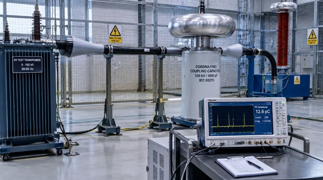
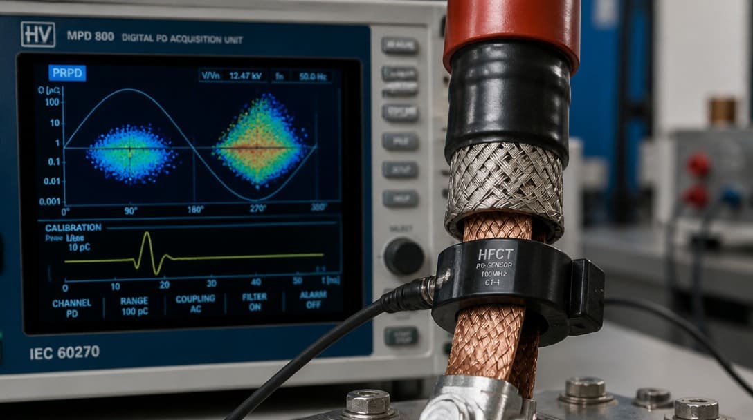
Require the test voltage to be expressed relative to the assembly’s rated voltage—for example, 1.3 U₀ or 1.3 times the rated phase-to-ground voltage. Confirm the test duration and whether the measurement uses a high-frequency current transformer clamped around the ground lead or a coupling capacitor in the test circuit. These details change what the measurement actually captures.
| Component / Insulation Type | Reference Standard | Baseline Test Voltage | Maximum Apparent Charge Limit (FAT) |
|---|---|---|---|
| Extruded XLPE / EPR Cable Body | IEC 60502-2 / ICEA S-94-649 | 1.73 U₀ (or 2.0 U₀) | ≤ 5 pC (Noise floor < 2 pC) |
| Factory-Molded Connectors & Joints | IEC 60502-4 / IEEE 404 | 1.5 U₀ ~ 1.73 U₀ | ≤ 10 pC |
| Pre-molded High-Voltage Terminations | IEC 60840 / CENELEC HD 629.1 | 1.5 U₀ | ≤ 10 pC |
| Inverter-Fed Motor Leads (Low-Voltage) | IEC 60034-18-41 / IEC 60664-1 | Peak-to-peak transient V_peak | No repetitive PD allowed (PDIV > 1.2 × peak transient) |
A pass/fail certificate without an apparent charge limit and test voltage cannot support a meaningful factory acceptance decision. It is only a statement that some partial discharge equipment was connected to the assembly at some point. Without the limit, there is no way to determine whether the result was 3 pC or 300 pC.
Specify that the report should include background noise level, calibration pulse verification, the measured discharge magnitude trace, and the test circuit arrangement. This allows source inspection to distinguish real partial discharge in the insulation from surface leakage, fixture noise, or a poorly grounded test setup.
What Goes Wrong in the Field When Partial Discharge Testing Is Skipped or Specified Loosely
Voids at molded or field-terminated connector interfaces become initiation sites. A cable assembly that passes routine factory acceptance checks can still develop partial discharge under normal operating voltage because those checks may not detect sub-critical discharge activity. The void remains latent until operating voltage and environmental stress push it into measurable discharge.
Contamination at cable lugs and stress-control interfaces creates surface discharge paths. If the factory acceptance test did not require a PD measurement, these defects can pass final visual and continuity inspection and fail only after installation, when partial discharge has already begun to track across the insulation surface.
Partial discharge can emerge only after thermal cycling. Heating and cooling opens micro-voids at material boundaries inside the insulation and at termination interfaces. A room-temperature PD test on a new assembly may miss a failure mechanism that appears after repeated load cycles. For high-voltage wire harness and cable assembly designs with thermal cycling duty, this gap needs to be considered before accepting a one-time room-temperature test as sufficient.
Altitude change lowers air density and reduces the voltage threshold for external discharge. An assembly qualified at sea level may show discharge at high-altitude installations unless the test and acceptance criteria account for operating altitude. This is a specification problem, not a manufacturing defect, but it changes the necessary PD test scope.
Comparing Suppliers That Include or Exclude PD Testing: A Practical RFQ Evaluation Table
Use a normalized evaluation table when comparing supplier responses. A supplier that lists “PD testing” without a limit scores lower than a supplier that states IEC 60270, ≤10 pC at 1.3 U₀, 60 seconds, and includes calibration data—because the second offer supports a meaningful acceptance decision.
| Supplier | Stated Standard and Circuit | Apparent Charge Limit | Test Voltage | Measurement Equipment | Calibration Data in FAT Report | Evaluation |
|---|---|---|---|---|---|---|
| Supplier A | IEC 60270, HFCT on ground lead | ≤10 pC | 1.3 U₀, 60 s | High-frequency current transformer | Noise floor and calibration pulse included | Acceptable if application margin is verified |
| Supplier B | “PD tested” only | Not stated | Not stated | Not stated | None | Cannot support factory acceptance |
| Supplier C | No PD test line item | N/A | N/A | N/A | N/A | Evaluate only if go/no-go checklist shows PD testing is not required |
Compare the cost of a dedicated test run against the catastrophic financial risk of an unverified field failure. For medium-voltage and inverter-duty OEM equipment, an uncalibrated PD test is practically useless, whereas a quantified FAT protocol safeguards field uptime. EDOM Electronics works alongside engineering teams during early DFM reviews to align connector creepage distances, evaluate shielding terminations against PD risk, and manufacture functional cable prototypes within 3–5 days for pre-compliance verification—ensuring that production lots meet verified IEC 60270 thresholds without unexpected NRE tooling delays.

Action Plan: Turning a Supplier’s PD Test Statement into a Source Inspection Decision
- Ask the supplier to confirm the specific IEC 60270 requirements, the apparent charge acceptance limit in picocoulombs, the test voltage as a percentage or multiple of rated voltage, and the duration of the test.
- Compare the stated limit and test voltage to your operating voltage, insulation system, and application environment using the go/no-go checklist before accepting the FAT line item.
- Require the FAT report to include the noise floor, calibration pulse verification, test circuit diagram, and the measured discharge magnitude trace so the certificate is auditable during source inspection or receiving inspection.
- If the supplier cannot provide these details, treat the PD test line item as unverified. Either reject the quote or require a pre-production sample test with third-party witnessing before approving the supplier’s FAT procedure.
For custom cable assembly and wire harness programs, partnering with an OEM that systematically documents drawing sign-off, crimp force verification, 100% electrical continuity, and visual inspection—as detailed in our guide on How Manufacturers Ensure Consistent Cable Assembly Quality—streamlines the broader FAT audit. However, partial discharge acceptance limits must still be explicitly defined as contractual engineering parameters prior to production release.
Frequently Asked Questions
What is the difference between PDIV and PDEV in IEC 60270 testing?
PDIV is the partial discharge inception voltage—the voltage at which discharges first appear when the test voltage is increased. PDEV is the partial discharge extinction voltage—the voltage at which discharges disappear when the test voltage is reduced. Comparing both values to the assembly’s normal and transient operating voltage helps determine whether there is enough margin before discharge activity begins.
What apparent charge limit in picocoulombs should I specify for a medium-voltage cable assembly?
Many OEM specifications use a limit in the 5–10 pC range for medium-voltage cable assemblies, but the correct number depends on insulation class, termination design, and application environment. The supplier should state the limit and the test voltage—such as 1.3 U₀—so the factory acceptance decision is based on a numeric threshold, not a generic pass/fail statement.
Can a supplier pass IEC 60270 PD testing with only a pass/fail certificate?
Not in a way that supports a meaningful factory acceptance decision. Without an apparent charge limit, test voltage, duration, background noise level, and calibration data, the certificate only shows that partial discharge test equipment was used. It does not show whether the assembly actually meets a defined insulation quality requirement.
Does partial discharge testing apply to low-voltage cable assemblies?
Usually not as a routine factory acceptance test. Low-voltage assemblies below roughly 3.3 kV typically do not require IEC 60270 PD testing unless the application creates special conditions such as inverter-fed drives, high-altitude operation, wide thermal cycling, or safety-critical duty. In those cases, a defined PD test with stated PDIV and PDEV values may be justified.
Key Takeaways
- A supplier’s “PD testing” line item without an IEC 60270 reference, apparent charge limit in picocoulombs, test voltage, and duration is not an acceptance test—it is a placeholder.
- Use the go/no-go checklist first: operating voltage above roughly 3.3 kV, XLPE/EPR/silicone insulation with molded or field terminations, inverter-fed or high-altitude duty, and supplier test capability all shift the decision toward specifying PD testing.
- PDIV and PDEV provide more useful engineering information than a single pass/fail result because they show the voltage margin between normal operation and discharge inception.
- Accept only PD test reports that include background noise level, calibration pulse verification, and the measured discharge magnitude trace so source inspection can distinguish real partial discharge from fixture noise.
- Normalize supplier quotes with a comparison table; a loosely specified PD test can pass an assembly that fails in the field, while a properly specified test reduces installation-stage failure risk.
For broader quality inspection and export packaging support across OEM cable assembly and wire harness programs, learn more about production follow-up, appearance inspection, continuity documentation, and export-ready packing.