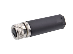
Direct answer: An M12 connector is a circular industrial connector (see our What Is a Connector? A Practical Overview for OEM Buyers) with an M12x1 locking thread, standardized across the IEC 61076-2 series (including IEC 61076-2-101 for signals/100M Ethernet, IEC 61076-2-109 for 10G X-coded data, and IEC 61076-2-111 for power) for device and network interconnections. Coding letters determine mating compatibility and function, so A-coded, D-coded, and X-coded parts are not interchangeable despite sharing the same thread.
At a Glance
M12 is a mechanical series, not an electrical specification. A-coded M12 parts carry sensor/actuator I/O and DC power; D-coded parts serve 100BASE-TX Industrial Ethernet; X-coded parts support multi-gigabit Ethernet. Releasing a BOM safely requires matching the coding letter, pin count, and IP rating to the port function and installation environment.
The BOM Problem: A-Coded vs D-Coded M12 Part Numbers Without Function Context
Consider a procurement manager reviewing a supplier BOM that lists M12 A-coded and D-coded part numbers without port mapping, function labels, or line-side location data. The new production line build is waiting, and the natural move is to treat M12 as one interchangeable part because the M12x1 thread and the 4-pin count appear identical. The hidden trap is that the coding keyway and contact layout differ. An A-coded plug and a D-coded socket will not mate without mechanical damage, and a D-coded Ethernet part cannot carry a sensor power loop simply because the pin count matches.
The failure often appears when the harness reaches the panel builder, not when the BOM is approved. The fix is not a gender changer or adapter; it is a re-terminated cable with the correct coding letter, keyway orientation, and contact assignment. Before approving any M12 line item, run the three-column check: coding letter against function, pin count against the I/O map, and IP rating against washdown, temperature, or vibration exposure.
M12 Connector Basics: Why the Series Name Is Not a Specification
The M12x1 thread describes only the mechanical coupling: a nominal 12 mm diameter with 1 mm pitch. It does not state electrical function, coding, pin count, gender, termination type, or environmental rating. Mechanical dimensions and coding interfaces are anchored to the IEC 61076-2 standard series (such as IEC 61076-2-101, -109, and -111 depending on coding), while ingress protection is verified against IEC 60529. Buyers who treat “M12” as a complete specification are ordering a housing family, not a finished interconnect solution.
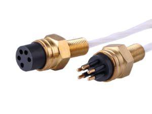
The coding keyway is a physical orientation feature inside the connector that prevents mating between different coding letters. Under the IEC 61076-2 standards, a connector will mate only with its matching coding, so a D-coded plug cannot substitute for an A-coded socket without forcing the keyway. A BOM-ready M12 part number must state the coding letter, pin count, gender, termination type, and IP rating. If any of those fields is missing, the part is not yet ready for release.
- M12x1 thread: 12 mm nominal coupling diameter, 1 mm pitch, used across the M12 family.
- IEC 61076-2 series (e.g., -101, -109, -111): dimensional, coding, and electrical interface frameworks governing signal, high-speed Ethernet, and power M12 circular connectors.
- IEC 60529: defines IP ingress-protection ratings such as IP67, which indicates dust-tight protection and protection against temporary water immersion.
- Coding keyway: prevents mismating between A-coded, D-coded, X-coded, and other M12 variants.
M12 Coding-to-Application Decision Tool
The following decision tool maps M12 coding letters to typical functions, pin counts, and electrical ratings. Use it as a screenshot-ready reference when a BOM lists a coding letter without a defined port role. The electrical ratings shown are the M12 coding ratings referenced in IEC 61076-2 specifications, not arbitrary product ratings.
| M12 Coding | Typical Signal or Power Role | Common Pin Count | Electrical Rating Reference | Mating Note |
|---|---|---|---|---|
| A-coded | Sensor/actuator I/O, DC power | 3–12 poles (4-pin and 5-pin most common) | Pin-dependent per IEC 61076-2-101: 250 V / 4 A (3–4 pin); 60 V / 4 A (5-pin); 30 V / 2 A (8-pin) | Use for PLC I/O, sensors, valves, and basic DC power loops |
| D-coded | Industrial Ethernet 100 Mbit/s | 4 poles | Ethernet datacom rating per IEC 61076-2 | Not a substitute for sensor power loops even with 4-pin count |
| X-coded | Industrial Ethernet up to 10 Gbit/s | 8 poles | High-speed datacom rating per IEC 61076-2 | Keyway differs from A-coded and D-coded |
| S-coded | AC power, motor & frequency inverter connections | 3–4 poles (2+PE or 3+PE) | Rated 630 V AC / 12 A (per IEC 61076-2-111) | Use only for AC power circuits; PE pin mates first (FMLB) |
| T-coded | DC power distribution, fieldbus power | 4 poles | Rated 63 V DC / 12 A (per IEC 61076-2-111) | Replaces legacy power connectors in 24V/48V DC trunks |
| L-coded | High-current DC power for PROFINET & distributed I/O | 4–5 poles (4 or 4+FE) | Rated 63 V DC / 16 A (per IEC 61076-2-111) | High-power standard replacing bulky 7/8″ connectors |
| B-coded | Fieldbus and Profibus applications in some industrial networks | Verify device datasheet | Application-specific; verify against network specification | Do not assume compatibility without the network standard |
| C-coded | Legacy AC power applications | Verify device datasheet | Application-specific; verify against equipment datasheet | Less common; confirm mechanical keyway before ordering |
The practical rule is simple: an A-coded connector is for sensor/actuator and DC power loops, a D-coded connector is for 100 Mbit/s Industrial Ethernet, and an X-coded connector is for high-speed Industrial Ethernet. The pin count alone never resolves the function.
Pin Counts and Gender: Mapping 4-Pin, 5-Pin, and 8-Pin Layouts to the I/O Map
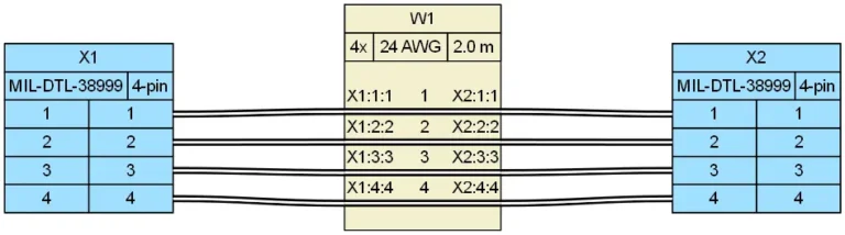
Pin count does not define function; contact arrangement and coding do. A 4-pin A-coded sensor/actuator connector and a 4-pin D-coded Ethernet connector share the same pin count but have different keyway positions and contact assignments. The two cannot be interchanged, even if the BOM line item only says “M12 4-pin.”
Common layouts include:
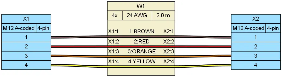
- 4-pin A-coded: sensor/actuator I/O, often with two signal conductors and two power conductors.
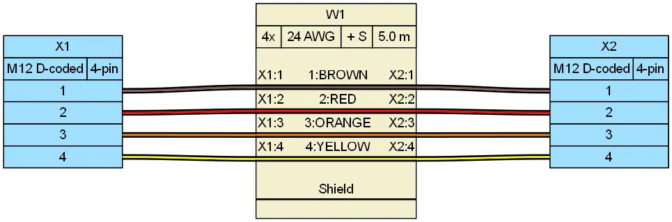
- 4-pin D-coded: 100BASE-TX Industrial Ethernet with four contacts assigned to Ethernet pairs.
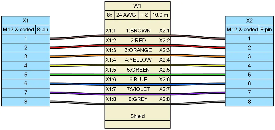
- 8-pin X-coded: high-speed Industrial Ethernet with eight contacts arranged for multi-gigabit transmission.
- 5-pin A-coded: sensor or actuator device with additional signal or shield connection.
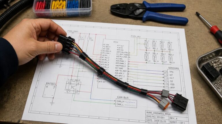
Gender selection also matters. A male or female panel-mount connector, a field-attachable version, or an overmolded cable assembly must match the I/O map and the physical wiring direction. For OEM projects, the I/O map should drive both connector selection and the wire harness manufacturing routing, labeling, and termination decisions. Procurement should never approve a pin count without seeing the port function and contact assignment.
IP Ratings and Environmental Survival: IP67, Washdown, Vibration, and Temperature
IP67 under IEC 60529 means the assembly is dust-tight and protected against temporary water immersion under defined test conditions. That rating applies only to the rated assembly in the mated condition. It does not automatically mean every boundary is sealed at every cable entry. A mating face can be IP67 while the cable jacket, termination boot, or panel gasket remains vulnerable.
Washdown exposure adds chemical compatibility, thermal shock, and high-pressure jet considerations far beyond static IP67 immersion. A standard IP67 connector that survives a bench water tank will rapidly fail in a food, beverage, or pharmaceutical washdown line. For caustic, high-pressure cleaning environments, OEM buyers must specify IP69K (per ISO 20653)—which validates survival against 80°C water jets at 80 to 100 bar—paired with corrosion-resistant stainless steel (e.g., AISI 316L) coupling nuts and ECOLAB-certified chemical-resistant elastomers (such as FKM/Viton or EPDM seals rather than standard NBR).
For any M12 assembly, specify the IP rating at three boundaries: the mating interface, the cable termination, and the panel-mount sealing surface. If only the connector bulkhead is rated, the field wiring side may compromise the entire system.
Field Failure Patterns: When Coding or IP Rating Is Assumed Instead of Verified
Several failure modes recur in M12 projects because coding or IP rating was assumed from a partial BOM rather than verified from the full part number and drawing set.
- Washdown failure after bench pass: a sensor connector passes continuity and function testing but fails after washdown because only the mating face was sealed. The cable end was not IP67, and water enters through the termination boot.
- Panel-builder substitution: an Ethernet drop cannot be plugged because the panel builder substituted a D-coded cable for an A-coded sensor port. The keyway does not match, and the connector cannot mate without physical force.
- Pin count assumption: a D-coded Ethernet part is assumed to carry a sensor power loop because both have four pins. The contact layout and current rating differ, so the circuit either does not work or creates a safety risk.
- Late-term BOM discovery: the mismatch appears at panel build or after installation, not in the BOM review, because the coding letter was omitted from the part number.
These failures are procurement-facing problems because the missing information lives in the supplier documentation, not in the electrical design. The preventive control is to verify the coding letter, pin count, and IP rating before the purchase order is committed and the line build begins.
The Three-Column BOM Check: Coding, Pin Count, and IP Rating Before Releasing the Line
The three-column check turns a partial M12 BOM into a release-ready specification. Run each line item through these columns before ordering.
| Check | Question | Pass Condition | Red Flag |
|---|---|---|---|
| Column 1: Coding letter vs function | Does the coding letter match the port role? | A-coded for sensor/actuator and DC power; D-coded for 100 Mbit/s Ethernet; X-coded for high-speed Ethernet | D-coded listed for a sensor I/O point; X-coded listed for a standard I/O terminal |
| Column 2: Pin count vs I/O map | Do pin count and contact assignment match signal and power budget? | Pin count follows the I/O map including spare pins and power conductors; orientation matches field wiring direction | 4-pin A-coded and 4-pin D-coded treated as interchangeable; 8-pin X-coded ordered for a 4-pin I/O port |
| Column 3: IP rating vs environment | Does the assembly survive washdown, dust, temperature, and vibration at both mating face and cable entry? | IP rating meets installation conditions for the complete mated assembly, including cable jacket, termination, and panel gasket | Only the mating face is rated; cable entry is unspecified; no chemical compatibility data for washdown |
If a BOM omits the coding letter or IP rating, request the full part number, drawing, or sample before ordering. For OEM buyers who need this verification done quickly, production-coordinated suppliers such as EDOM Electronics can review BOM line items against port functions, confirm coding and pin assignments, coordinate samples, and provide inspection before the production order is released.
From Verified BOM to Production-Ready M12 Cable Assemblies
After coding, pin count, and IP rating are verified, the next decisions are termination method, cable structure, and panel-mount sealing. A production-ready M12 assembly file should lock the cable jacket material, conductor gauge, shield construction, overmold or field-attachable termination, and the continuity and insulation test limits.
For example, an M12 X-code to RJ45 waterproof cable, such as the EDOM M12 X-Code to RJ45 waterproof cable used for Industrial Ethernet, is specified at 30 V, 1 A per contact, conductor resistance ≤5 Ω Max, insulation resistance ≥10 MΩ at DC 300 V, 8 pins, AWG 24 conductors, TPU/NBR materials, and IP67 in the mated condition per engineering drawing specs. That level of specificity is what separates a purchasing placeholder from a manufacturable assembly.
Once the specification is locked, a custom cable assembly program should include drawing review, connector matching, sample confirmation, termination, continuity testing, appearance inspection, and export-specific packaging. RoHS-compliant product options should also be confirmed where applicable. This prevents line-down rework, panel-builder substitution, and post-installation washdown failures that trace back to an incomplete BOM.
Frequently Asked Questions
Can I use a D-coded M12 connector in place of an A-coded M12 if both have 4 pins?
No. The coding keyway positions differ under IEC 61076-2-101, so the connectors will not mate without mechanical damage. The contact assignments are also different: A-coded is for sensor/actuator I/O and DC power, while D-coded is for 100 Mbit/s Industrial Ethernet.
What is the difference between M12 A-coded and X-coded connectors?
A-coded connectors support sensor/actuator signals and DC power across 3 to 12 poles, with electrical ratings scaling by contact density under IEC 61076-2-101 (250 V / 4 A for 3–4 poles, 60 V / 4 A for 5 poles, and 30 V / 2 A for 8 poles). X-coded connectors support Industrial Ethernet up to 10 Gbit/s with 8 poles. The keyway geometry and contact density are different, so the two are not interchangeable.
Does an IP67-rated M12 connector guarantee washdown survival?
Not by itself. IP67 under IEC 60529 means dust-tight and protected against temporary water immersion, but the rating applies to the mated assembly. The cable jacket, termination boot, panel gasket, and chemical compatibility must also match the washdown, temperature, and vibration environment.
How do I verify an M12 part number before ordering?
Request the full part number including coding letter, pin count, gender, termination type, and IP rating. Review the drawing or sample, compare the coding letter to the port function, the pin count to the I/O map, and the IP rating to the installation environment. For OEM programs, suppliers such as EDOM Electronics can support drawing review, connector matching, sample confirmation, and pre-production inspection.
What does M12x1 mean?
M12x1 is the thread designation: a nominal 12 mm coupling diameter with 1 mm pitch. It describes the mechanical locking thread only, not the coding, pin count, electrical function, or environmental rating.
Key Takeaways
- M12x1 is a mechanical thread specification, not a functional rating. Coding letter, pin count, gender, and IP rating must be stated separately.
- A-coded M12 connectors serve sensor/actuator I/O and DC power; D-coded connectors serve 100 Mbit/s Industrial Ethernet; X-coded connectors support multi-gigabit Ethernet.
- A 4-pin A-coded connector and a 4-pin D-coded connector cannot be interchanged because the keyway and contact assignments differ under IEC 61076-2-101.
- IP67 only protects the rated mated assembly. Cable entry, termination, and panel-mount sealing must be verified for washdown, vibration, and temperature exposure.
- Check every M12 BOM line item against three columns: coding letter versus function, pin count versus I/O map, and IP rating versus environment.
Explore electronic connector sourcing and specification support for OEM, distributor, and export-facing M12 interconnect programs.