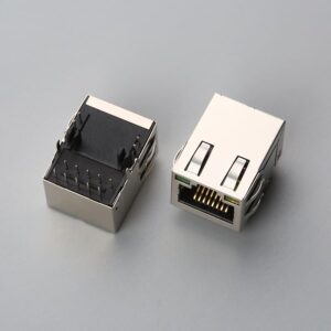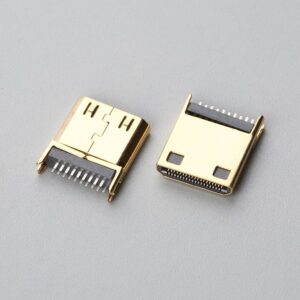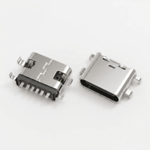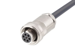
Direct answer: A PCB connector is an electromechanical interface component with a defined contact pitch, termination style, and mated stack height, engineered to join a printed circuit board to another board, wire harness, or flexible circuit while maintaining electrical continuity and mechanical retention. For a broader component taxonomy, see our guide on What Is a Connector? A Practical Overview for OEM Buyers.
At a Glance
Before comparing PCB connector quotes, verify paired interface specifications rather than pin count alone. The minimum decision fields are contact pitch, row spacing, mounting style, mated stack height, exact mating part number, contact plating thickness, termination type, and environmental rating. While assembly workmanship is inspected against IPC/WHMA-A-620[1] for wire terminations and IPC-A-610 for solder joints, neither workmanship standard validates paired mechanical compatibility—missing interface fields must be verified directly against manufacturer datasheets and EIA-364 test reports.
When the BOM Lists Three Unfamiliar Board-to-Board Part Numbers
A design team BOM arrives with three board-to-board connector part numbers. The supplier quote lists pitch, stack height, and plating in shorthand. The verbal description from the engineer says something different. At the same time, two quotes for the same 40-pin outline show different prices, and the connector drawing does not explain why. The first reaction is to compare pin count and outline and assume interchangeability. That is the wrong starting point.
A PCB connector is a paired interface, not a commodity footprint. Two connectors can share the same pin count, pitch, and outline and still differ in contact wipe, insertion depth, and soldering profile. The correct diagnostic before any price comparison is a one-page interface checklist: pin count, pitch, row spacing, mounting style, mated stack height, mating connector part number, contact plating, termination type, and operating environment.
PCB Connector Types on a Quote: What to Confirm Before Approving Each One
For procurement managers, the practical question is not “what is this connector family?” but “what must be confirmed before I approve this line item?” Each connector family carries different approval risks.
- Pin header: Confirm mated stack height and contact plating before accepting a pin header line item. A pin header with the right pin count but the wrong post length or tin flash can cause the plastic housing to mate while the contact normal force is outside the design range. Request the mated stack height and the mating socket part number.
- Box header: Confirm the mating header part number, polarization, and stack height. Box header retention clips and latch details matter less than whether the shrouded housing accepts the exact mating connector style and keying orientation.
- Board-to-board connector: Confirm mated stack height, row spacing, and contact wipe compatibility with the exact mating connector. A board-to-board connector that matches the board footprint but has different insertion depth can still fail electrically in the field.
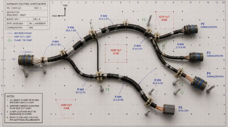
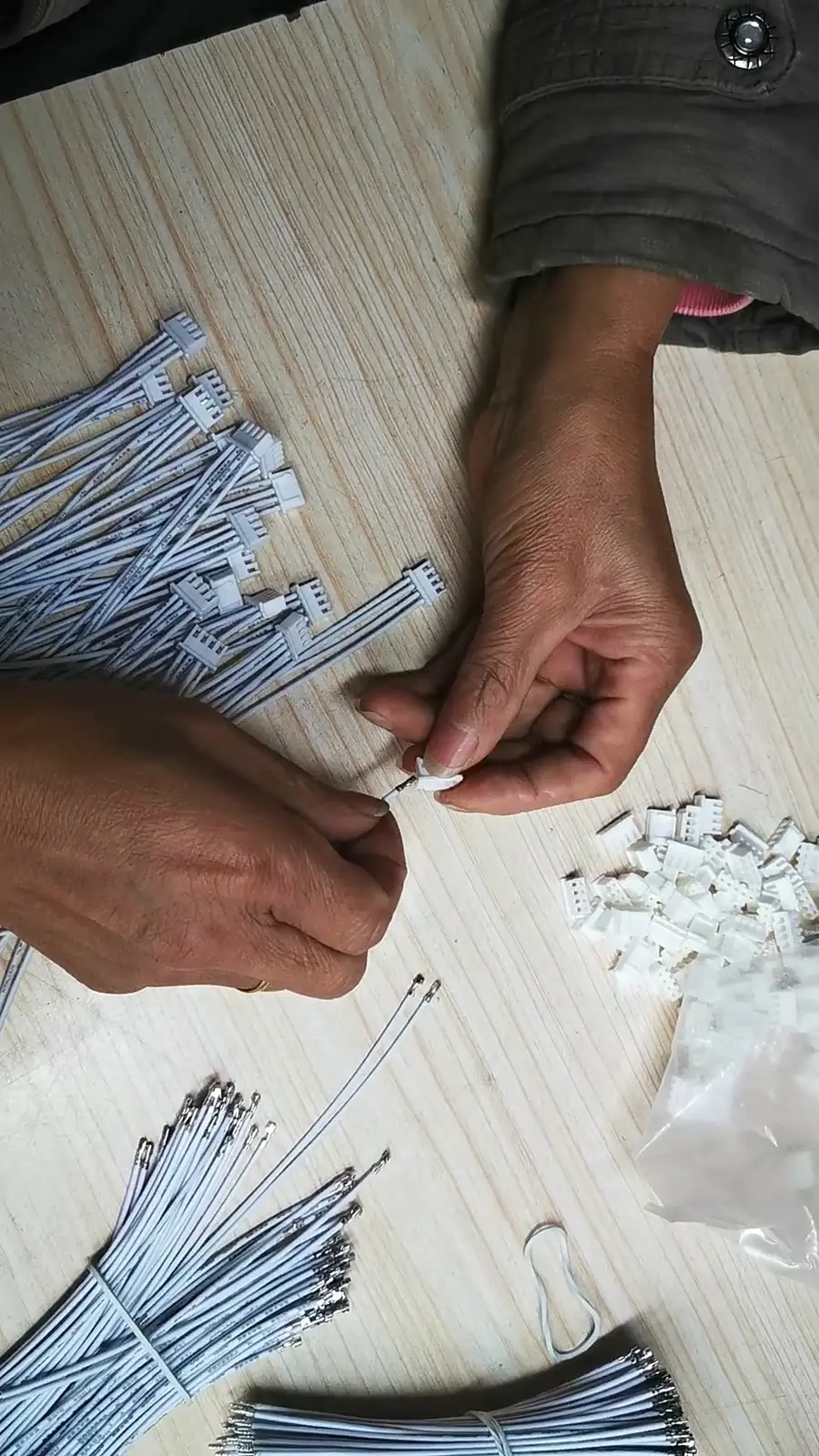
- Wire-to-board connector: Confirm termination style, wire gauge range, and whether the housing accepts the actual terminal series being quoted. This is where cable assembly design fails most often: the housing fits but the crimp terminal belongs to a different series or AWG range.
- FPC connector: Confirm pitch, actuator type, and flex thickness. An FPC connector with the correct pin count but a front-flip actuator and the wrong flex thickness can produce unstable contact pressure after assembly.
- DIN 41612: Confirm standard row assignment, mating connector class, and mounting orientation before comparing quotes. DIN 41612 is not one connector; row assignment and class must align with the backplane or card cage.
- Card edge connector: Confirm plating thickness, keying, and board thickness range rather than accepting a generic gold flash callout. Card edge connectors rely on board contact pad geometry, so plating thickness and board tolerance are part of the interface.
In all cases, pin count is the least useful approval criterion. The paired interface data drives whether a quote is technically comparable.
PCB Connector Quote-Check Before You Compare Prices
The table below turns a supplier quote into a missing-field diagnostic. Before comparing price, every row should receive a clear answer. Keep this table ready when reviewing supplier quotes in an RFQ or BOM approval cycle.
| Quote Field | Go/No-Go Engineering Question | What to Request / Typical Spec Benchmark |
|---|---|---|
| Pin count & keying | Does the quote match the BOM pin count and polarization orientation? | BOM cross-reference, keying code, and pin-1 orientation drawing |
| Contact pitch | Does the center-to-center pitch match the mating part and PCB footprint? | Dimensional drawing (e.g., 0.5mm, 1.0mm, 1.25mm, 2.0mm, or 2.54mm) |
| Row spacing | For dual-row connectors, is row-to-row spacing compatible with the housing? | Housing mechanical drawing with row pitch tolerance |
| Mounting style | Is SMT, through-hole (DIP), or press-fit matched to the reflow/wave profile? | Recommended PCB land pattern and SMT lead coplanarity (typically ≤ 0.10mm) |
| Mated stack height | Does the board-to-board distance fit the enclosure Z-axis envelope? | Mated stack height drawing and effective contact wipe length |
| Mating part number | Does the quote specify the exact mating housing and terminal part numbers? | Complete mating P/N (housing + crimp terminal series) and manufacturer |
| Contact plating | Are finish, plating thickness, and nickel underplate explicitly quantified? | Full plating callout (e.g., Gold flash 1–3 µin vs. 15–30 µin Gold over 50 µin Nickel) |
| Current & voltage rating | Does the per-pin ampacity and dielectric withstand voltage meet circuit loads? | Current derating curve (A/pin) and housing flammability rating (e.g., UL94 V-0) |
| Operating environment | Do housing polymer and plating survive reflow and field operating conditions? | Temp rating (e.g., -40°C to +105°C; LCP/PA9T for 260°C reflow) and mating cycles |
The rule is simple: if a quote cannot answer these fields, it cannot be compared on price. The comparison may be between two different interfaces that only appear to share a footprint.
Two 40-pin connectors can have the same outline, the same pitch, the same pin count, and different prices. The natural assumption is that the higher-priced quote is overpriced. That assumption often misses the real reason: a PCB connector is a system of termination style, contact metallurgy, and mating height, not a single footprint check.
Even when the plastic housings snap together, contact wipe and insertion depth may be wrong. The housing latch is a retention feature; it does not prove that the contact beam has achieved the intended normal force. A connector that fits the footprint can have insufficient wipe because the mated stack height or contact spring design differs. The result is high resistance or intermittent contact under vibration.
Acceptance standards highlight this split. IPC-A-610 provides acceptance criteria for solder termination and electronic assembly work, but it does not evaluate whether the mated connector pair has the correct insertion depth. IPC/WHMA-A-620 defines acceptance criteria for crimped and wire termination work, but it similarly assumes the correct terminal and housing combination has been selected. For wire harness manufacturing programs, the same rule applies: crimp acceptance criteria assume the terminal, wire gauge, and housing are already matched. A quote without a mating connector part number or plating callout cannot be confirmed against those standards because the acceptance criteria begin after the correct interface has been specified.
Field Failure Modes That Quotes Rarely Reveal
Superficially similar quotes can hide field failure risks that do not appear on a unit price line. Procurement managers should treat these failure modes as specification-level checks, not optional engineering details.
- Flash-gold wear and pore corrosion: A thin gold flash (typically < 3 µin) over an under-plated nickel barrier can wear through after just 10 to 20 mating cycles, exposing base phosphor bronze or brass to oxidative pore corrosion. A quote stating only “gold” without thickness (µin) and nickel underplate (typically 50 µin minimum) cannot guarantee durability across the equipment’s service life.
- Tin-gold fretting corrosion: Mating a tinned crimp terminal to a gold-plated PCB header creates a galvanic and mechanical mismatch. Under micro-vibration or thermal expansion, the softer tin transfers onto the gold surface and oxidizes rapidly, forming insulating fretting debris that spikes contact resistance above 50–100 mΩ.
- SMT lead coplanarity and reflow warpage: Substituting a low-cost connector with nylon (PA66) insulator material into a lead-free SMT reflow profile (peak 250°C–260°C) causes housing blistering and lead coplanarity exceeding the standard 0.10mm threshold, resulting in open solder joints or fine-pitch solder bridging. High-temp polymers like LCP, PPA, or PA9T must be specified for SMT headers.
- Insufficient contact wipe length: Even when plastic housings snap together, mismatched stack heights or altered contact beam geometry can reduce effective contact wipe below the minimum threshold needed to scrub surface oxides, causing intermittent signal drop under shock.
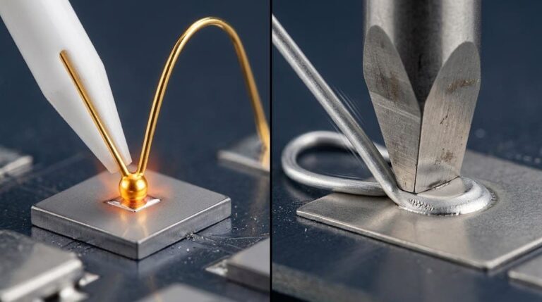
- Pad cratering from cable extraction stress: In wire-to-board SMT connectors without mechanical solder tabs (fitting nails), operator pull force or heavy wire harness routing transfers mechanical torque directly to the copper PCB pads, fracturing the laminate during servicing.
None of these failure modes appears on a standard unit price quote. That is why the one-page interface checklist matters before price comparison.
What to Ask the Supplier Before Comparing Prices
Use the following questions as a supplier clarification request. They should go back with the RFQ or be answered before BOM approval.
- Require the mating connector part number as a mandatory quote line, not a note or verbal assurance.
- Ask for contact plating as finish, thickness, and underplate, not only “gold” or “tin.”
- Ask how termination will be inspected: IPC-A-610 for solder joints and IPC/WHMA-A-620 for crimp and wire dress where applicable.
- Ask for mated stack height and insertion depth in writing, preferably on the drawing or quote.
- Ask for environmental assumptions: temperature range, humidity, vibration, and expected insertion cycles relevant to the equipment.
For OEM programs where board-level connector selection dictates wire harness routing and terminal tooling, EDOM Electronics provides upfront DFM review, pin-to-pin cross-reference validation (matching Molex, JST, TE, and Hirose footprints), and rapid 3–5 day harness prototyping. Validating mating terminal crimp height, pull-force compliance, and inspection and export packaging before mass production prevents costly PCB re-spins and line-down delays.
Frequently Asked Questions
Is a PCB connector interchangeable if it has the same pin count and pitch?
Not necessarily. The same pin count and pitch do not confirm mated stack height, contact plating, termination type, or the exact mating connector part number. A footprint match is not a paired interface match.
What is the minimum information to request on a PCB connector quote?
Request the exact mating connector part number, pitch, row spacing, mounting style, mated stack height, contact plating finish/thickness/underplate, termination type, and operating environment. If any field is missing, the quote is not ready for price comparison.
Why do two 40-pin board-to-board connector quotes differ in price?
Differences in contact plating thickness, underplate, insulator material, termination quality, and connector series can all affect price even when pin count and outline appear identical. The higher-priced quote is not necessarily overpriced; the interfaces may be materially different.
What standards apply to PCB connector solder and crimp acceptance?
IPC-A-610 covers solder termination and assembly acceptance for electronic assemblies. IPC/WHMA-A-620 covers crimped and wire termination work. Both standards assume the correct connector interface has already been selected and do not replace paired connector design verification.
How should an OEM buyer compare PCB connector quotes before looking at price?
Use a go/no-go quote checklist. Confirm pin count, pitch, row spacing, mounting style, mated stack height, mating connector part number, contact plating, termination type, and environment. Only after all fields are answered should price become a decision factor.
Key Takeaways
- Approve a PCB connector only after confirming paired interface fields, not pin count and outline.
- Always request the exact mating connector part number and a clear plating callout on the quote.
- Use the quote-check table as a go/no-go diagnostic before any price comparison.
- Identical pitch and footprint do not mean identical contact wipe, insertion depth, or termination behavior.
- A quote missing the mating connector part number or plating callout should be returned for clarification before BOM approval.
Need to validate a second-source PCB connector or lock in a matched wire-to-board harness assembly without risking BOM mismatches? Explore our electronic connector supply and DFM selection support, or send us your BOM and mating drawings for a fast engineering cross-check.