If you’re specifying a cable assembly and the operating environment hasn’t come up in the conversation yet, it should be the first thing on your list — not an afterthought.
A specialized cable assembly is a purpose-built interconnect combining conductors, connectors, overmolding or strain relief, and a protective jacket designed for a specific operating environment, used to transmit power, signals, or data reliably in demanding OEM equipment.
What Counts as a Specialized Cable Assembly?
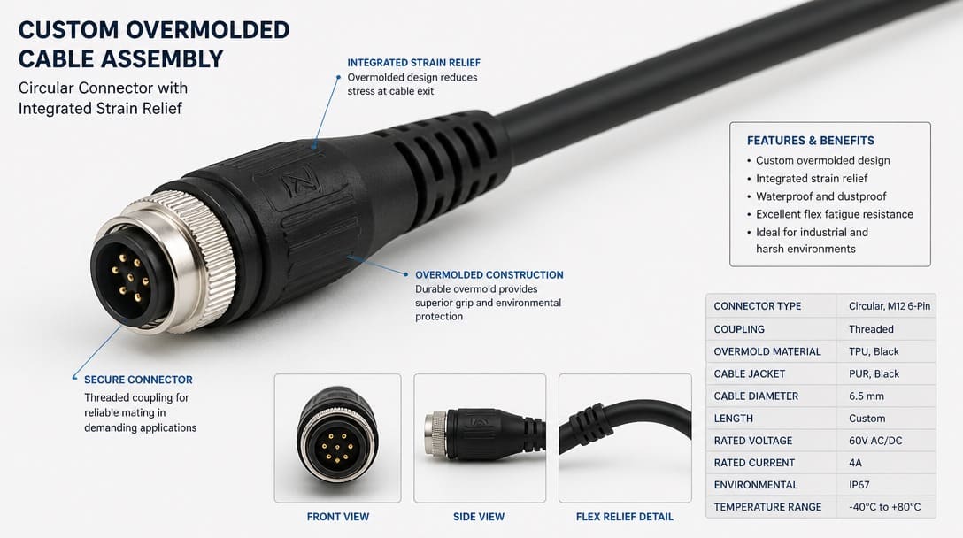
A specialized cable assembly is more than a bundle of wires with connectors on both ends. It includes engineered termination methods, environmental sealing where required, and a mechanical structure that protects the electrical connection during installation, operation, and service. Typical construction elements include conductor sizing by AWG, insulation rated under UL 758[1], connector interfaces such as M12 connectors or MIL-DTL-38999 circular connectors for aerospace and defense applications, overmolding for environmental protection, and strain relief to manage mechanical stress at termination points. Where compliance matters, RoHS-compliant materials restrict ten substances — including lead, cadmium, hexavalent chromium, PBB, PBDE, and four phthalates — to a maximum 0.1% by weight, or 0.01% for cadmium.
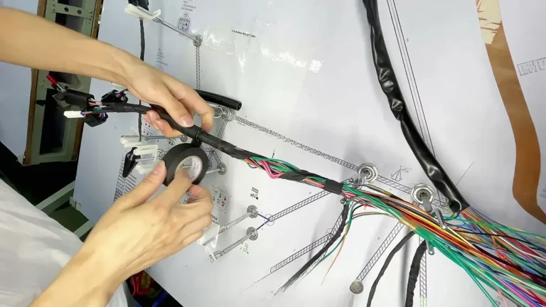
The distinction between a cable assembly and a wire harness remains a common source of confusion for procurement teams and design engineers. A wire harness primarily organizes and routes multiple wires or cables within a product. It may include terminals, connectors, labels, and sleeving, but it does not typically provide the sealed connectors and environmental overmolding found in a specialized cable assembly. For buyers evaluating wire harness manufacturing, the acceptance criteria defined in IPC/WHMA-A-620 for cable and wire harness assemblies apply to both categories, but the environmental and connector integration expectations differ significantly.
| Parameter | Cable Assembly | Wire Harness |
|---|---|---|
| Primary function | Transmit power, signals, or data with environmental and mechanical protection | Bundle, route, and organize conductors within a product |
| Environmental protection | Often includes sealed connectors, overmolding, and water-blocked conductors | Typically limited to looming, tape, or basic sleeving |
| Connector integration | Frequently overmolded or epoxy-potted at connector terminations | Usually terminated with standard crimped or soldered contacts |
| Typical OEM use case | Outdoor equipment, washdown areas, robotics, industrial machinery | Internal equipment wiring, control panels, routing harnesses |
| Acceptance standard | IPC/WHMA-A-620 workmanship classes, depending on product class | IPC/WHMA-A-620 workmanship classes, with lower class often acceptable for internal routing |
Why Operating Environment Changes Everything in OEM Design
Many OEM design teams treat cable assemblies as generic parts. The initial discussion focuses on connector pitch, pin count, and conductor gauge — often before anyone asks where the assembly will actually live in the equipment. That sequence creates avoidable failures. Moisture, extreme temperature, tight installation space, and vibration each change the required connector sealing, conductor insulation, overmold geometry, strain relief, and shielding approach. When these factors are considered late in the design cycle, fixes frequently require changes to enclosure tooling, PCB layout, or assembled cable routings.
The upstream impact is real but often underestimated. A connector that works in a dry indoor cabinet may fail in a humid agricultural environment without IP67-rated sealing. A cable rated for room-temperature operation may cold-crack in a marine application. A comfortable bend radius on a bench may be impossible inside a compact robotics joint. When environment is not mapped before drawing release, the project inherits redesign cost and schedule pressure that could have been avoided.
The Operating Environment Checklist Before Any Cable Assembly Specification
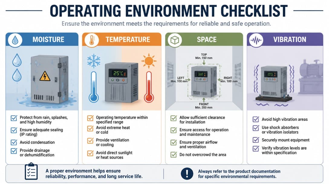
Before connector selection or quotation, the following four conditions should be documented. They translate directly into material, geometry, and test requirements.
- Moisture exposure: Define whether the assembly faces splash, washdown, sealed enclosure, or outdoor exposure. This determines the need for IP67-rated connectors, overmolding, grommets, or water-blocked conductors. IP67 indicates the component is dust-tight and protected against temporary immersion in water.
- Temperature range: Record fixed operating and storage temperatures. These values affect UL 758-rated wire insulation selection, AWG derating for elevated temperatures, cold-flex performance, and connector material choice.
- Installation space: Map the available volume for connector bodies, overmold dimensions, bend radius, and strain relief before finalizing cable lengths. Space is often the first constraint violated when a design is rushed.
- Vibration or mechanical stress: Identify flex cycles, abrasion points, cable weight, and retention requirements. These factors drive strain relief design, conductor construction, and jacket material selection.
Before you move to connector selection or quotation, lock down moisture exposure, temperature range, installation space, and vibration. Early environment review prevents later overmold, shielding, and fit corrections.
The Overmold Dimension Problem: Why Internal Layout Must Be Designed Together
Overmolding is one of the most common causes of late-stage cable assembly revisions, and the reason is deceptively simple. An overmold must be thick enough to fully encapsulate internal solder joints, connector terminations, and strain relief elements without thin walls or voids. If the material is too thin, mechanical failure and moisture ingress become real risks. At the same time, the overmolded body must fit within the available installation space: enclosure cutouts, mating cavity depth, mounting clips, and clearance to adjacent components. Both constraints are physical limits that cannot be negotiated after tooling is cut.
When both constraints are tight, cable assembly design cannot be treated as an isolated outsourced task. The internal PCB layout, grounding scheme, and shield termination inside the device must be planned as part of the cable assembly design. A connector placed too close to an enclosure wall may not accept the required overmold height. A grounding point that is convenient for the board designer may leave no practical path for a low-impedance shield drain. Late overmold changes often force redesign of enclosure openings and board positions. This is precisely the kind of cost that disappears when environment and installation space are mapped before the first drawing is released.
Shielding: Foil, Braid, or Combined—and When It Matters
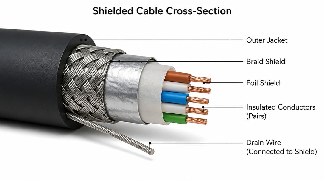
Shielding is not a default requirement for every cable assembly, but it becomes necessary when cables run near switching power electronics, motor drives, sensors, or when EMI/EMC requirements apply to the system. The choice among foil, braid, and combined shielding has direct consequences for performance, flex life, and mechanical packaging.
Foil shields provide effective high-frequency coverage in a light, compact form and typically require a drain wire for termination. Braid shields offer low-frequency EMI attenuation, mechanical strength, and better flex life compared to foil alone. Combined foil-plus-braid construction addresses both high-frequency interference and mechanical robustness in one cable structure. Shield termination is part of the assembly design; an ungrounded or improperly terminated shield can degrade performance instead of improving it. In circular connector applications, MIL-DTL-38999 connectors often integrate shield termination directly into the connector body, making connector choice part of the shielding decision for aerospace and defense platforms.
| hield Type | Frequency Effectiveness | Flex Life / Mechanical Durability | Typical Optical Coverage | Primary Application |
|---|---|---|---|---|
| Aluminum Foil | High (>10 MHz, RFI) | Moderate (Prone to fatigue cracking under continuous dynamic flex) | 100% | Static routing, compact enclosures, high-density sensor wiring |
| Tinned Copper Braid | Low to Mid (<10 MHz, EMI) | High (Superior physical strength and flex fatigue resistance) | 70% – 95% | Industrial machinery, continuous-flex robotics, high-vibration harnesses |
| Foil + Braid Combination | Full Spectrum (Dual Protection) | High (Braid protects foil from mechanical shear) | 100% composite | Factory automation, servo motor drives, medical diagnostic equipment |
What to Include in a Cable Assembly Drawing to Avoid Redesign Cycles
A production-ready cable assembly drawing includes far more than pinout and wire gauge. The most effective drawings begin with a brief description of the operating environment and installation location. This context helps the supplier’s engineering review catch fit and performance issues before sample approval. The drawing should also specify the installation envelope, mating connector part numbers or interface standards, cable outer diameter, length tolerance, bend radius, overmold dimensions, and strain relief geometry.
Material and compliance requirements belong on the same drawing: RoHS status, UL 758-rated wire types, operating temperature range, and any flammability or chemical exposure notes. Inspection and test expectations should also be listed, including continuity, pinout verification, appearance inspection, and any special packaging for export or cleanroom use. For international shipments, quality inspection and export packaging requirements often need to be defined before quotation.
We regularly see cable assembly inquiries where the drawing shows connector types and wire gauge, but nothing about where the assembly will be installed. When the answer turns out to be inside a sealed enclosure in a humid environment, the entire overmold approach needs to change.
Suppliers such as EDOM Electronics support OEM buyers with requirement review, connector matching, sample coordination, production follow-up, inspection, and export-ready packaging for custom cable assemblies and wire harnesses. This kind of early production-coordinated review identifies conflicts that a drawing-only RFQ process can miss.
Specialized Cable Assemblies Across Application Areas
The same environmental logic applies across agriculture, robotics, automotive, and marine applications, although each sector emphasizes different variables.
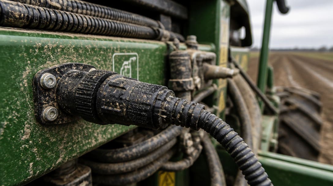
Agriculture wiring assemblies face dust, washdown, vibration, and weather exposure simultaneously. These assemblies typically require high-integrity sealing, abrasion-resistant jackets, and strain relief designed for repeated flexing around moving equipment.
For dynamic automation and robotic arms, interconnects face compound stresses from multi-axis torsion, continuous bending, and tight packaging constraints. For a comprehensive breakdown of connector selection, shielding trade-offs, and overmold dimension rules in continuous-motion paths, see our engineering guide on rugged robotics cable assembly design considerations. For instance, transitioning from standard multi-conductor PVC wiring to high-strand-count conductors (e.g., 26 AWG with 65/44 bare copper stranding) paired with a tough PUR jacket reduces the minimum dynamic bend radius from 10× outer diameter (OD) down to 5×–6× OD. This allows reliable operation through over 5 to 10 million flex cycles in articulated joints while holding the overall cable diameter within a ±0.15 mm envelope for strict raceway clearance.
Automotive and marine harness contexts share this same discipline: map temperature, moisture, vibration, and installation space before finalizing drawings. For harsh, salt-spray environments, review our guide on what OEM buyers should verify when sourcing a marine wire harness manufacturer to prevent salt-fog wicking and unsealed crimp failures. To ensure these constraints are met during production, learn more about Evaluating Automotive Wire Harness Manufacturers for OEM Projects.
Across all of these application areas, the common thread is that connector choice, conductor sizing, overmold geometry, and shielding must follow environment and installation constraints — not precede them. A design that starts with environment constraints rolls into production faster and with fewer concessions.
From Environment Requirements to Production-Ready Specialized Cable Assemblies
The logical sequence for any specialized cable assembly project is unchanged: start with the operating environment, then translate it into connector sealing, insulation materials, AWG sizing, overmold dimensions, shielding, and strain relief. That sequence reduces the chance of discovering a fit or performance problem after tooling is locked. Working with a supplier who reviews drawings, samples, specifications, packaging, and delivery expectations early helps identify issues before they become field failures. For OEM teams moving from a target application or sample concept to production-ready connection products, explore custom cable assembly solutions that support this environment-first approach.
Frequently Asked Questions
What is the difference between a cable assembly and a wire harness?
A cable assembly combines conductors, connectors, overmolding or strain relief, and a protective jacket to transmit power, signals, or data in a specific environment. A wire harness primarily bundles and routes conductors for organization and protection, typically without sealed connectors or environmental overmolding.
When should an OEM specify a specialized cable assembly instead of an off-the-shelf cable?
When the operating environment includes moisture, extreme temperature, tight installation space, vibration, or EMI exposure, a specialized cable assembly is usually required. Off-the-shelf cables may not meet sealing, flex-life, shielding, or dimensional requirements that a custom design can address.
What does IP67 mean for a cable assembly?
IP67 is an ingress protection rating indicating that the component is dust-tight and protected against temporary immersion in water. IP67-rated connectors and overmolded assemblies(see waterproof cable assembly manufacturing) are commonly specified for outdoor, washdown, and humid industrial environments.
Which standards apply to cable assemblies used in OEM equipment?
IPC/WHMA-A-620 defines acceptance criteria for cable and wire harness assemblies across three workmanship classes. IPC J-STD-001 covers soldered electrical and electronic assembly requirements, while IEC 60352 addresses solderless connections such as crimped, insulation-displacement, and press-in terminations. UL Safety Standard and RoHS compliance may also apply depending on the product and region.
Key Takeaways
- A specialized cable assembly is an application-specific interconnect, not a generic part; it differs from a wire harness in environmental sealing, connector integration, and overmolding.
- Operating environment — moisture, temperature, space, and vibration — must be documented before connector selection or quotation.
- Overmold dimensions cannot be separated from internal PCB layout, grounding, and shield termination when installation space is tight.
- Shielding choices among foil, braid, and combined construction depend on EMI requirements, flex life, and termination strategy.
- Detailed drawings and early supplier review prevent redesign cycles that arise from missing installation context.