MC4 is a single-pole electrical connector(see our What Is a Connector? A Practical Overview for OEM Buyers) originally developed by Multi-Contact (now Stäubli) for photovoltaic systems. But in the field, ‘MC4’ has become shorthand for a whole family of lookalikes—and the difference between a genuine MC4 and an ‘MC4-compatible’ part is where field failures begin.
Direct answer: MC4 is a specific single-contact connector series by Stäubli, now widely copied under ‘MC4-compatible’ labels. A genuine MC4 is designed to meet IEC 62852[1] for PV connectors, with a locking collar, UV-stable housing, and a crimp or spring contact rated for the current. Compatibility is not guaranteed by appearance.
MC4 Is a Brand, Not a Category—Why the Distinction Matters
In procurement documents, “MC4” often appears without a manufacturer or part number. That single omission creates risk. MC4 is not a generic product category like an M12 circular connector or an RJ45 jack. It is a specific DC connector series owned by Stäubli, originally designed for photovoltaic systems. The original design uses a locking collar, a defined sealing stack, and a specified crimp or spring contact. Those three elements are not decorative; they are part of the electrical and mechanical interface.
A datasheet that lists only “MC4 connector” invites the buyer to accept a lookalike. Without a manufacturer and series designation, the crimp contact geometry, sealing sleeve compound, contact plating, and locking collar detent force remain uncontrolled. In a photovoltaic system, that interface is a series DC point under continuous load and outdoor exposure. A mixed mating interface—one brand of plug with another brand of socket—may fit physically but may not meet the mated-pair requirements of IEC 62852 or UL 6703.
Engineers and installers should treat MC4 as a controlled interface, not a commodity shape. The cost difference between a qualified connector and an unchecked copy is small compared with the cost of a hot joint or arc fault on a rooftop.
What “MC4-Compatible” Actually Means in Sourcing Documents
“MC4-compatible” is a manufacturer claim, not an independent certification. In most purchasing documents, it means only that the plastic housing profile resembles an MC4. It does not confirm that the crimp contact geometry, sealing sleeve material, contact plating thickness, or locking collar detent strength match the original design. Those four parameters are where field failures start.
Mixing a no-name MC4-compatible plug with a genuine Stäubli MC4 socket can feel tight at first. The locking collar may engage, and a simple continuity check may pass. But after hundreds of thermal cycles, the mating interface can develop fretting corrosion and intermittent opens. The reason is microscopic: the contact surfaces move against one another as temperature changes, and if the two contact geometries or plating systems were not designed as a mated pair, that movement produces wear and oxidation.
For procurement, the phrase “MC4-compatible” should be treated as an incomplete specification. A usable requirement identifies the exact manufacturer, connector series, contact type, wire gauge range, and test standard—such as IEC 62852 for PV DC connectors. Without those elements, the buyer is relying on appearance.
The Four Hidden Parameters a Photo Doesn’t Show
A visual incoming inspection cannot evaluate four parameters that determine whether an MC4-compatible connector will survive in a photovoltaic system. The outline looks right, but the connector’s long-term performance depends on details below the housing surface.
Crimp contact geometry and tooling profile
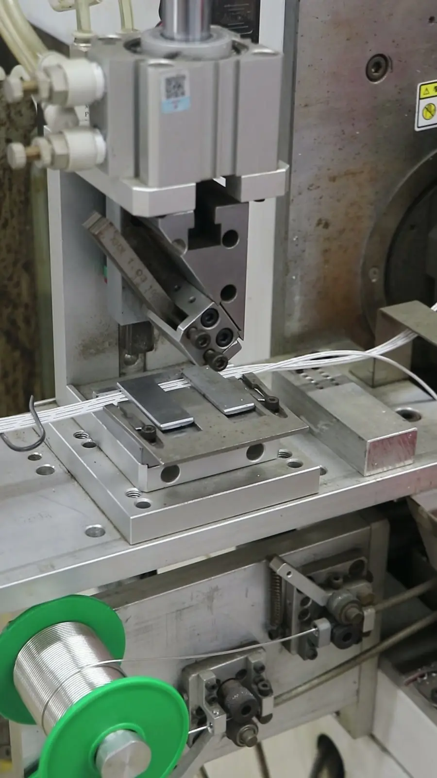
The contact barrel must match the crimp tool’s anvil profile. A cheap open-barrel crimp tool can crack or unevenly deform the contact barrel, leaving one side over-crimped and the other under-crimped. We regularly see connectors that pass visual incoming inspection but fail during crimp pull-force testing—the contact barrel geometry is different from the tool’s anvil profile. The part looks right; the crimp tool doesn’t know it’s wrong.
Sealing sleeve material and UV resistance
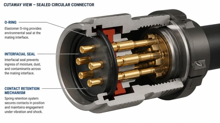
The sealing sleeve sits inside the housing and is responsible for the IP67 performance of the DC connector. If the sleeve is made from a low-cost silicone or EPDM compound without adequate UV stabilizers, it can harden, shrink, or tear after prolonged sun exposure. The groove position also matters: a sleeve that sits one millimeter out of position may not compress fully when the locking collar is tightened.
Contact plating and DC corrosion
Tin, silver, and flash plating behave differently in dry indoor, humid, and coastal environments. In a DC circuit, any small gap or metallurgical mismatch can become a corrosion cell. Mixed plating metallurgies between a plug and socket promote fretting under thermal cycling, gradually raising contact resistance and creating heat.
Locking collar detent strength
The locking collar is not just a convenience feature; it is a safety mechanism. A weak detent allows partial disengagement under wind vibration or thermal movement. That partial disengagement can create clearance, arcing, and intermittent contact. A photo cannot measure detent force.
Engineering Benchmark: Genuine MC4 vs. Low-Cost “MC4-Compatible” Clones
| Parameter | Genuine Stäubli MC4 Specification | Uncontrolled MC4-Compatible Clones | Failure Mechanism |
|---|---|---|---|
| Contact Interface | Silver-plated copper alloy with MULTILAM™ technology | Flash tin-plated stamped brass or thin flash-silver | Fretting corrosion, contact resistance climb (ΔR > 5 mΩ), thermal runaway |
| Housing Material | Hydrolysis & UV-resistant polyamide (UL 94-V0) | Recycled PPO/PC blends without long-term UV stabilizers | Micro-cracking under thermal cycling, locking latch breakage |
| Locking Force | Snap-in detent requiring tool release (NEC compliant) | Loose mechanical tolerance or brittle retention clips | Spontaneous decoupling under wind buffeting; DC series arc fault |
| Continuous Operating Temp | -40°C to +85°C (upper limit +105°C) | Degrades rapidly above +70°C | Sleeve embrittlement, IP67 seal failure, ground faults |
Compatible vs. Interchangeable: What IEC 62852 and UL 6703 Require
IEC 62852 is the product standard for PV DC connectors, defining electrical, mechanical, environmental, and safety requirements for connectors used in photovoltaic systems. UL 6703 is the equivalent North American standard for connectors and components used in photovoltaic systems. Both standards treat a connector as a system, not a standalone part.
Compliance with IEC 62852 or UL 6703 does not make connectors cross-manufacturer interchangeable. Under North American electrical codes (NEC 690.33(C)), mating connectors from different manufacturers is explicitly prohibited unless they are certified and Listed as an intermateable pair. A plug from Manufacturer A and a socket from Manufacturer B may each pass standalone type testing, but cross-mating them voids system certifications, invalidates fire insurance, and frequently fails mated-pair testing for temperature rise at rated current, dielectric withstand, IP67/IP68 sealing, and thermal cycling behavior.
This is why the phrase “MC4-compatible” can be misleading. A connector may be “compatible” with the MC4 shape but never tested as a mated pair with a genuine Stäubli MC4 socket. The only reliable interchangeability check is a physical mated-pair test against the exact connector already installed in the field. Datasheet images and housing profiles are not enough.
MC4 Verification Checklist Before You Order
Before committing to a purchase order, the following five-point checklist reduces the risk of accepting a connector that looks right but fails in service.
| Verification Step | What to Check | Why It Matters | Acceptance Criterion |
|---|---|---|---|
| 1. Crimp height & pull force | Calibrated locator tooling matching contact barrel (4 mm² / 6 mm²) | Asymmetrical crimping causes localized resistance and thermal runaway | Meets IEC 60352-2 pull-off force (≥ 310 N for 4 mm²; ≥ 360 N for 6 mm²); crimp cross-section analysis reveals zero void porosity |
| 2. Ingress protection & seal | UV-stabilized silicone or high-grade EPDM, seated in defined groove | Prevents capillary moisture ingress and IP67/IP68 breakdown over 25-year service | Compression ratio within 25–35%; passes helium leak / immersion test (1 m, 30 min) |
| 3. Contact plating | Plating material and thickness for the environment | Tin vs silver affects DC corrosion and fretting | Matches dry, humid, or coastal exposure |
| 4. Sample mating | Physical sample with the exact field connector | Confirms mechanical detent and electrical interface | Firm lock, stable contact, no looseness |
| 5. Wire fit | Wire gauge and insulation outside diameter | Strain relief and sealing range must match | No forced insertion or visible gap |
For OEM projects that require more than a loose connector, the same verification process should be applied before custom cable assembly work begins. A verified connector saves rework and protects the downstream harness.
Field Failure Modes Specific to MC4 in PV Systems
Most MC4-related failures in photovoltaic systems are not detected by a simple end-to-end continuity check at installation. The common field failure modes share a pattern: they appear after sustained current, thermal cycling, or moisture exposure.
- Water ingress: a torn, undersized, or mis-seated sealing sleeve compromises IP67 protection and starts corrosion paths.
- Hot joints: asymmetrical crimps create localized resistance and heat that may only appear after sustained current and thermal cycling.
- Arcing: loose locking collars produce intermittent contact, carbon tracking, and potential DC arc damage.
- Contact fretting: mixed plating metallurgies degrade contact resistance under temperature swings and humidity.
Each of these failures can exist in a connector that passes a visual inspection and a basic continuity test on installation day. The failure appears later, when the system is already in the field.
From Verified Connector to Production-Ready Cable Assemblies
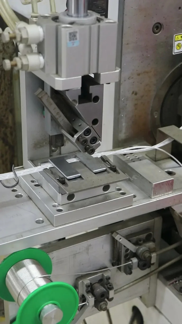
After the exact MC4-compatible connector and mating pair are verified, the next risk moves to termination quality. Stripping, crimping, continuity testing, appearance inspection, and export packaging all affect long-term performance. A qualified connector terminated with the wrong tool or an inconsistent crimp height is still a field failure waiting to happen.
Mitigating cross-mating risk in commercial and utility-scale PV builds requires tight DFM (Design for Manufacturability) collaboration before volume production. At EDOM Electronics, our engineering team audits wire-to-contact tolerances, provides automated crimp-force monitoring data, and delivers turnkey PV extension harnesses with 3–5 day rapid prototyping. By integrating batch-level crimp cross-section analysis and 100% low-resistance testing upfront, we minimize termination-induced field arc risks before your container ships. For integrated trunk lines and combiner harnesses, our wire harness manufacturing line follows strict IPC/WHMA-A-620 Class 3 assembly protocols.
Custom cable assemblies and wire harnesses can be built around MC4-compatible connectors only after the exact mating pair and crimp tooling are locked. The remaining steps—visual appearance inspection, continuity testing, and quality inspection and export packaging—confirm that the finished assembly is ready for shipment and installation.
Frequently Asked Questions
Is MC4 a connector standard or a brand?
MC4 is a brand-specific DC connector series originally developed by Multi-Contact, now part of Stäubli. It is not a generic industry standard. The relevant product standards for PV DC connectors are IEC 62852 and UL 6703.
Can I mix MC4-compatible connectors from different suppliers?
Not reliably. Even if each connector individually meets IEC 62852, the mated pair may not have been tested together. Mixing brands can feel tight at installation but develop fretting corrosion, intermittent opens, or hot joints after thermal cycling.
What is the difference between MC4-compatible and MC4?
“MC4-compatible” usually means the housing shape resembles an MC4. It does not confirm that the crimp contact geometry, sealing sleeve material, contact plating, or locking collar detent strength match a genuine Stäubli MC4.
What should I check before ordering MC4 connectors for a PV project?
Confirm the crimp tool matches the exact contact specification, verify the sealing ring is UV-stable and correctly positioned, check contact plating for the environment, obtain a physical sample and mate it with the field connector, and confirm wire gauge and insulation outside diameter fit the strain relief.
Does a simple continuity check catch MC4 connector defects?
No. Many MC4 field failures—water ingress, hot joints, arcing from loose collars, and contact fretting—appear only after thermal cycling, moisture exposure, or sustained current. Continuity testing at installation is insufficient.
Key Takeaways
- MC4 is a specific Stäubli connector series, not a generic product category. “MC4-compatible” does not guarantee mating performance.
- Four invisible parameters—crimp contact geometry, sealing sleeve material, contact plating, and locking collar detent strength—separate a qualified PV DC connector from a visual copy.
- Connectors that individually meet IEC 62852 or UL 6703 are not automatically interchangeable; the mated pair must be tested together.
- A five-point verification checklist before ordering reduces the risk of field failures that continuity testing cannot detect.
- After connector verification, termination quality, inspection, and export packaging determine whether the cable assembly survives in service.
For OEM and wholesale buyers moving from connector selection to production, explore custom cable assembly and wire harness solutions using MC4-compatible connectors with coordinated sample confirmation, crimp verification, and export-ready packaging.