Direct answer: A cable assembly shield termination is the electrical and mechanical interface where the braided or foil shield connects to a connector, backshell, or chassis, and its high-frequency impedance—rather than DC continuity—primarily determines EMI/RFI behavior; low-impedance 360° termination with proper system grounding suppresses radiated emissions, while pigtail drain wires and floating shells degrade shielding effectiveness.
At a Glance
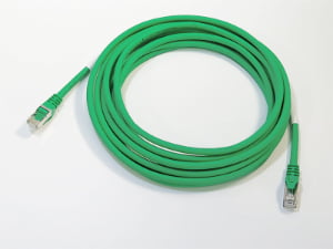
Passing DC continuity on a shielded cable does not prove that the shield is RF-grounded. Termination inductance, ground path length, connector shell bonding, and one-end versus both-end grounding all change how common-mode noise becomes radiated or conducted emissions. The shield termination drawing should therefore state which termination method is intended—360° ferrule contact or a drain wire—together with shell-to-chassis bonding and grounding topology, because workmanship acceptance alone does not establish EMI/RFI performance.
Are you chasing an intermittent EMI field failure that already passed DC continuity—or reviewing a pigtail drain wire drawing?
Many EMI/RFI investigations begin from one of two situations. A field failure report describes intermittent noise on a data cable whose braided shield is crimped to a ferrule and passes bench continuity testing. Or an engineer pauses over a drawing that calls out a pigtail drain wire to chassis and cannot reconcile the passing continuity reading with the radiated emissions result. The hidden assumption in both cases is that DC continuity from shield to ground proves effective termination.
The problem is that a multimeter measures low-frequency resistance, not the impedance the shield presents to common-mode noise at the frequencies where EMI/RFI problems appear. A braided shield or foil shield can show near-zero DC resistance while still creating a high-impedance path if the drain wire is long, the braid is gathered into a partial solder connection, or the connector shell is not bonded to system ground. The diagnostic path below therefore moves through termination type, grounding topology, shell bonding, and the acceptance gap left by mechanical workmanship criteria.
Should you replace the pigtail drain wire with a 360-degree shield termination?
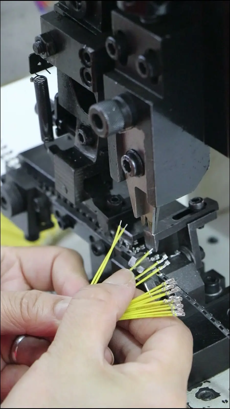
The core design decision is whether the shield should be gathered into a pigtail termination or captured around the full connector circumference in a 360-degree shield termination. A pigtail drain wire creates a long inductive ground path. That added series inductance raises transfer impedance and can turn common-mode noise into radiated or conducted emissions at higher frequencies, even when the drain wire passes a continuity test.
A braided shield should be compressed around the full circumference of the connector ferrule so that the return current has a low-impedance path across the connector interface. A foil shield often requires a drain wire because the foil itself is not robust enough for direct termination, but the drain wire must be kept as short as possible. A solder sleeve applied to a drain wire can still leave a high-impedance stub if the path from the sleeve to chassis is long or if the drain wire is routed away from the shield instead of following the cable axis.
Should both shield ends be hard-grounded, or should one end use an RC network?
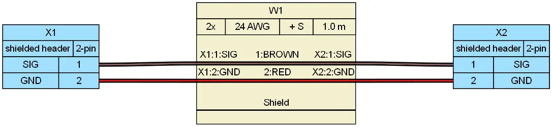
Grounding topology changes the return current path and the risk of ground loops. Single-point grounding avoids low-frequency ground loops by preventing current from circulating through the shield between two chassis points. But a long cable with only one grounded end can behave like a high-frequency antenna because the far end of the shield is not terminated to a defined reference.
An RC network at the far end provides a compromise. It blocks low-frequency ground-loop current while still providing a controlled high-frequency path to chassis. This approach is appropriate when cable length is significant, when the two ends sit on chassis planes with different ground potential, or when low-frequency noise is present on the ground return. Hard-grounding both ends across different potential planes can create circulating ground-loop currents that inject noise into sensitive circuits and appear as intermittent EMI/RFI in the field.
Is the connector shell actually bonded to system ground, or is it a floating antenna?
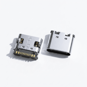
A 360-degree shield termination into a connector is only effective if the conductive backshell and shell-to-panel contact are low-impedance and bonded to system ground. The shield path does not end at the ferrule; it continues through the connector shell, across the mating interface, and into the chassis or enclosure ground.
A floating connector shell, an anodized or painted mating surface, or a panel cutout without grounding fingers can leave the shield referenced to no useful ground. In that condition, the shell itself can become a radiator even when the cable shield is terminated correctly inside the connector. The mechanical drawing should therefore show metal-to-metal contact, grounding fingers, and the absence of any insulating finish across the bond interface.

What does IPC/WHMA-A-620[1] Class 2/3 really verify—and what must be specified before it applies?
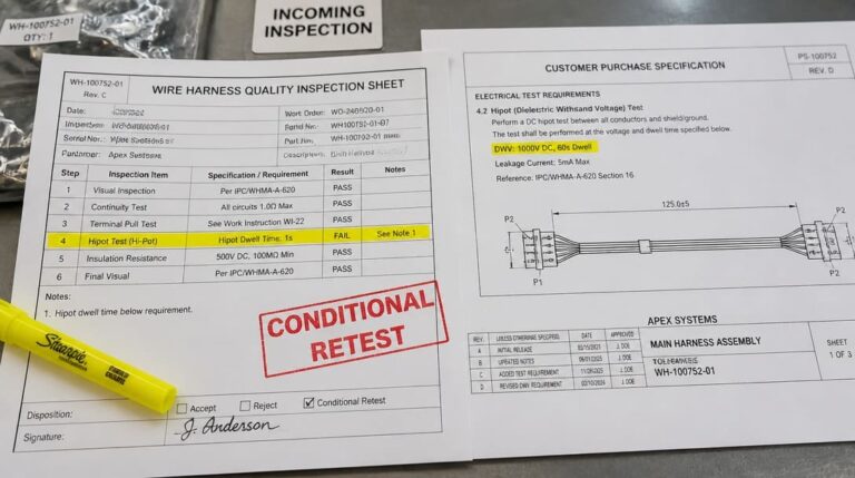
IPC/WHMA-A-620 defines acceptance criteria for cable and wire harness assemblies and establishes three workmanship classes with increasing inspection and documentation rigor. For shield termination, the standard addresses mechanical attributes such as braid capture, solder sleeve flow, strain relief, and visual acceptance of the finished assembly.
Passing IPC/WHMA-A-620 Class 2 or Class 3 does not by itself guarantee EMI/RFI performance. The standard verifies mechanical workmanship as covered in How Manufacturers Ensure Consistent Cable Assembly Quality, not transfer impedance, grounding topology, or radiated emissions margins. The design-level requirements must be specified before workmanship acceptance applies: 360° braid-to-ferrule contact, shell-to-system-ground bond, one-end versus both-end grounding, and far-end RC termination where the application requires it.
For OEM teams, a production partner experienced in wire harness manufacturing will review the drawing before cutting, stripping, and crimping so the specified shield capture method is translated into the sample build. Inspection records should align with quality inspection and export packaging steps to verify continuity, appearance, and shipment protection. Suppliers such as EDOM Electronics support OEM buyers with requirement review, connector matching, sample coordination, production follow-up, inspection, and export-ready packaging for custom cable assemblies and wire harnesses.
Which shield termination variables dominate transfer impedance in your design?
Among the variables under the designer’s control, termination inductance has the largest single effect on high-frequency shield performance. A long pigtail drain wire can add tens of nanohenries of inductance to the shield path, while a proper 360-degree shield termination keeps the ground path impedance low across the EMI/RFI frequency range. One-end versus both-end grounding then changes the return current path and the potential for ground-loop interference, and the conductive backshell bond determines whether that low-impedance path actually reaches system ground.
The practical design rule follows from this hierarchy: minimize termination inductance first by eliminating or shortening the pigtail, then manage grounding topology, and finally confirm that the connector shell is bonded metal-to-metal to the chassis. Solving the mechanical termination without addressing these downstream variables still leaves the shield vulnerable to field-level radiated emissions.
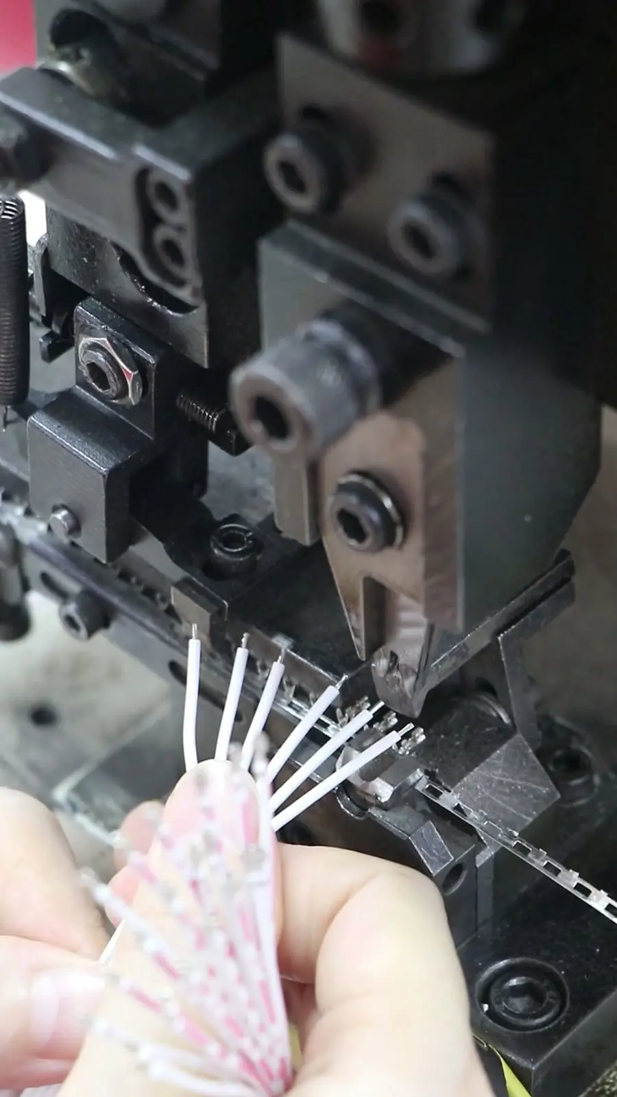
Shield Termination Go/No-Go Checklist: what should the drawing confirm before sign-off?
The following checklist converts the failure mechanisms above into drawing and specification acceptance criteria. Review each item before releasing a shielded cable assembly drawing or signing off on a pre-production sample.
| Checkpoint | Acceptance condition | Primary risk if missed |
|---|---|---|
| 360° braid-to-ferrule contact | Braid captured around the full connector circumference with low-impedance compression, not just a drain wire or partial solder connection | Long inductive ground path and radiated emissions at higher frequencies |
| Shell-to-system-ground bond | Conductive backshell and panel/chassis interface are metal-to-metal, low-impedance, and free of insulating coatings | Floating shell acts as a radiator; shield is not referenced to system ground |
| Ground-loop risk | Both ends hard-grounded only when ground potential difference is negligible; otherwise use one-end grounding plus an RC network at the far end | Circulating ground-loop current and intermittent EMI/RFI in the field |
| Transfer impedance validation | Impedance or transfer impedance check required at the design stage, not DC continuity alone | Passing continuity while failing high-frequency shielding effectiveness |
| Drain wire path | Drain wire kept short if used, or eliminated in favor of 360° termination | High-impedance stub; pigtail inductance dominated by path to chassis |
What nobody tells you about shield termination failures
Some shield termination failures are invisible on the bench and only appear after thermal cycling, vibration, or installation into a real chassis. Micro-oxidation under a non-gas-tight ferrule can pass initial continuity and later degrade into an intermittent high-impedance shield path. A floating connector shell can behave as an antenna even when the braided shield inside the cable is terminated correctly, because the shell lacks a low-impedance bond to system ground. And hard-grounding both ends across different potential planes can create ground loops that circulate current through the shield and inject noise into sensitive circuits.
When a cable assembly passes continuity but still fails intermittently in the field, the corrective action should not start with changing the cable type. Re-examine termination impedance, shell bonding, and grounding topology first. Those three variables—not the resistance reading—usually separate a mechanically acceptable shield termination from one that actually suppresses radiated emissions.
Frequently Asked Questions
Does passing a continuity test on a cable shield guarantee EMI/RFI performance?
No. Continuity testing verifies a low-resistance DC path. EMI/RFI performance depends on high-frequency impedance, ground path length, and connector shell bonding, none of which are captured by a standard continuity measurement.
When should a pigtail drain wire be used instead of a 360-degree termination?
A pigtail drain wire is sometimes used when the connector design cannot support full 360° capture or when a foil shield requires a drain conductor for termination. It should be kept as short as possible because the pigtail adds inductance to the ground path and degrades shielding at higher frequencies.
Can both ends of a shielded cable be hard-grounded?
Both ends can be hard-grounded only when the two chassis points are at essentially the same ground potential and the cable is short enough that ground-loop risk is low. When ground potential difference or cable length is significant, one-end grounding with an RC network at the far end is often a better strategy.
Does IPC/WHMA-A-620 Class 3 cover EMI/RFI shielding effectiveness?
No. IPC/WHMA-A-620 defines mechanical workmanship and visual acceptance criteria. It does not verify transfer impedance, grounding topology, or radiated emissions margins. Those requirements must be specified at the design level before the standard is applied.
What should OEM buyers specify before requesting a custom shielded cable assembly quote?
The RFQ should state whether 360° termination or a pigtail drain wire is required, how the conductive backshell must bond to the panel, whether one or both ends are grounded, and whether transfer impedance validation is required. A supplier such as EDOM can support this requirement review and sample confirmation before production.
Key Takeaways
- DC continuity is not a substitute for transfer impedance validation on shielded cable assemblies.
- 360° shield termination minimizes ground path inductance; pigtail drain wires degrade high-frequency shielding.
- One-end grounding and far-end RC termination help manage ground loops when chassis potential differences exist.
- The conductive backshell must bond metal-to-metal to system ground, or the connector shell can become a radiator.
- IPC/WHMA-A-620 Class 2/3 confirms mechanical workmanship, while EMI/RFI performance requires explicit design-level grounding and impedance requirements.
For OEM teams that need to turn shield termination requirements into a production-ready drawing, explore custom cable assembly solutions with connector matching, sample coordination, and export-ready packaging support.