Crimp pull force test AWG standards are gauge-specific tensile acceptance criteria used to verify that a crimp terminal mechanically retains a stripped conductor of a given AWG size under axial load, with thresholds referenced to IPC/WHMA-A-620 and the terminal manufacturer’s published minimum rather than a single harness-level pass/fail value.
The quality engineer who has just traced intermittent field failures to under-crimped junctions may recognize the sequence: continuity passed, the batch shipped, and the failures appeared only after vibration, thermal cycling, or an axial tug separated the crimp terminal from the conductor. The procurement or engineering reviewer facing this lot must now decide whether the supplier applied one generic pull-force value across mixed AWG sizes or verified each crimp terminal and barrel combination against the correct gauge-specific acceptance row.
Under-Crimped Junctions Passed Continuity: Are You Comparing Pull Force Against the Right AWG Row?
An under-crimped junction can pass electrical continuity because enough strands touch at zero mechanical load. The same termination slips or opens when the wire is pulled, vibrated, or thermally cycled. The acceptance question is therefore not whether the harness “has continuity,” but whether the measured tensile strength was evaluated against the exact AWG row and terminal barrel design used in production.
IPC/WHMA-A-620 treats cable and wire harness assembly acceptance as workmanship-class-based, with more rigorous inspection and documentation required for Class 2 and Class 3. It does not assign a single universal pull-force number to every AWG size. Instead, the acceptance threshold traces to the crimp terminal manufacturer’s published minimum for that specific conductor gauge and barrel size. A quoted value that cannot be traced to that source may be an unverified internal limit copied from another AWG row.
Procurement and engineering reviewers should require three things before accepting a suspect batch: the correct AWG-specific criterion, the escalation rule for destructive pull testing, and a documented disposition for borderline readings.
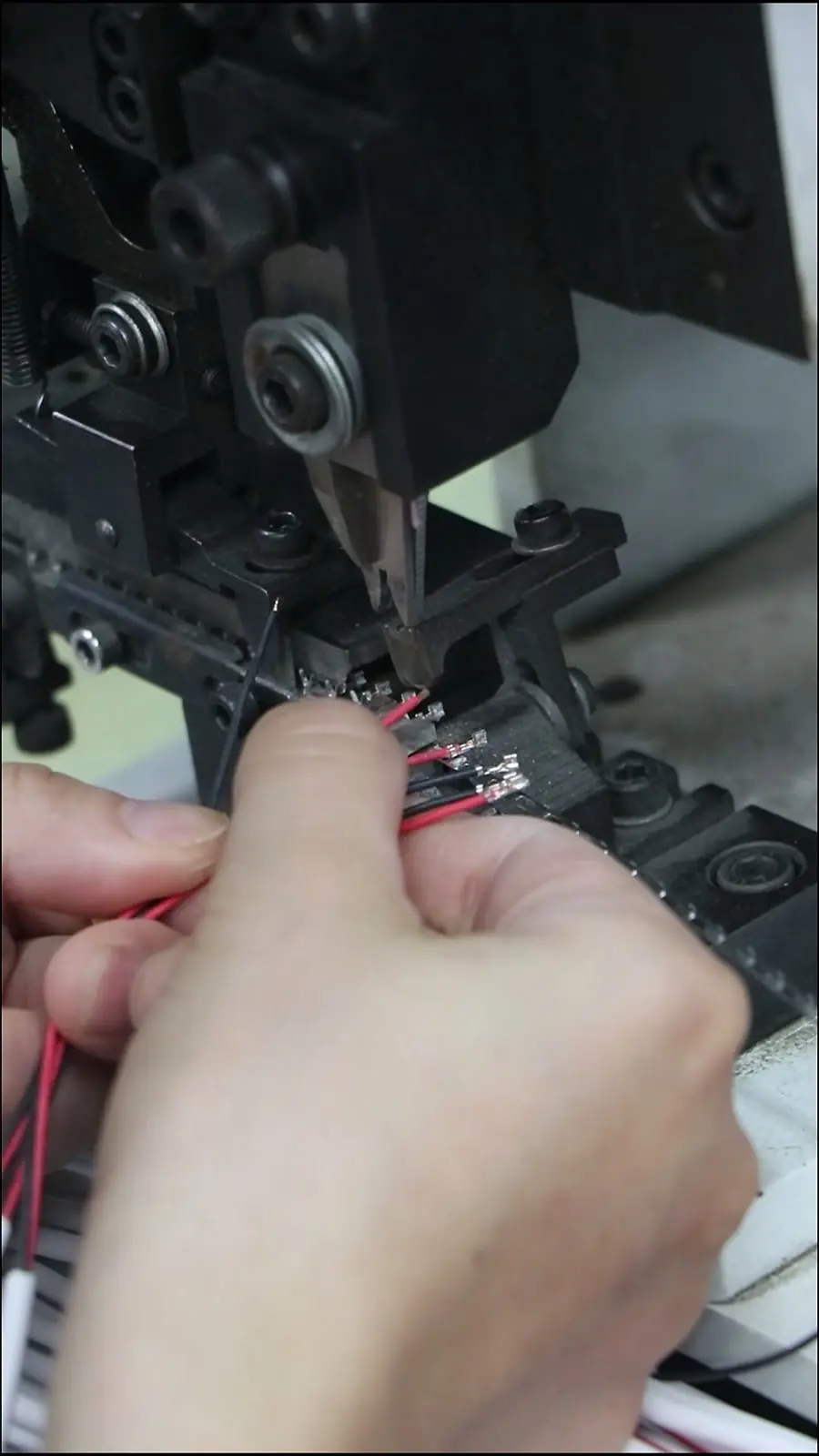
What Pull-Force Acceptance Criterion Should You Apply for Each AWG Size? Use This Go/No-Go Reference Checklist
Acceptance starts with the terminal manufacturer’s data. The go/no-go checklist below is intended for receiving inspection, as covered in our guide on cable tester functions, not as a pass/fail values table. The reviewer should fill in the terminal maker’s published minimum tensile value for each AWG and barrel combination. IPC/WHMA-A-620 tells the reviewer whether the supplier’s quoted value is a minimum tensile requirement or an internal limit; UL 486A and IEC 60352-2 supply connection-level performance context for termination methods, but the actual number comes from the terminal manufacturer.
Never copy a force value from a smaller or larger gauge row. A 22 AWG conductor in an oversized barrel and a 16 AWG conductor in an undersized barrel cannot share the same tensile strength boundary, even when both pass continuity.
| Checklist Field | What to Record at Incoming Inspection | Go/No-Go Decision Rule |
|---|---|---|
| AWG size | Actual conductor gauge, such as 26, 24, 22, 20, 18, or 16 AWG | Never copy a threshold from another AWG row |
| Crimp terminal type and barrel size | Terminal manufacturer part number, barrel ID, insulation support presence | Match terminal to AWG and wire construction |
| Minimum tensile value source | Terminal manufacturer’s published minimum (N or lbf) | Accept only when measured result meets or exceeds the maker’s minimum |
| Pull speed and method basis | From IPC/WHMA-A-620, UL 486A, IEC 60352-2, or terminal maker instruction | Apply axial pull rate and fixture condition |
| Measured pull force and failure location | Force value; wire break, strand pull-out, or contact retention loss | Record mode; a rolled-up value is not sufficient |
| Go/No-Go decision | Like-for-like AWG and terminal barrel comparison | Go only when all thresholds and failure modes align |
After applying the checklist, the next decision is destructive versus non-destructive verification. That choice belongs to the risk profile of the lot, not the convenience of the test lab.
When Should You Require Destructive Pull Testing Instead of Crimp Height Inspection?
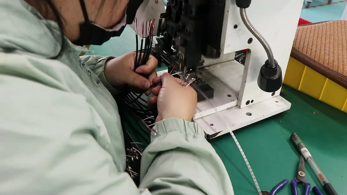
Crimp height inspection, as discussed in How Manufacturers Ensure Consistent Cable Assembly Quality?, is a non-destructive check that confirms the crimp die closed to a defined dimension. It supports process control after the pull-force baseline for that AWG and terminal combination has been confirmed. It does not prove contact retention or conductor hold under load.
Destructive pull testing uses a calibrated pull force tester to load the wire and crimp terminal axially until failure. The result is compared to the terminal manufacturer’s published minimum tensile value for the exact AWG and barrel size. Destructive testing is the required escalation when under-crimped junctions are suspected, when mixed AWG sizes share a single pass/fail value, or when contact retention must be proven under mechanical load.
| Inspection Condition | Crimp Height Inspection | Destructive Pull Testing |
|---|---|---|
| Suspected under-crimp or intermittent field failures | Not sufficient alone | Required |
| Mixed AWG sizes with one generic pass/fail value | High risk | Required per AWG and barrel combination |
| Known terminal maker crimp height window and stable process | Acceptable for ongoing control | Not required for every lot |
| New terminal, new tool, or new die qualification | Not sufficient alone | Required as baseline |
| Contact retention under load must be proven | Cannot verify | Required |
IPC/WHMA-A-620 references destructive testing as a verification method where crimp quality is in question. Even so, the pass/fail value always traces back to the terminal manufacturer’s published minimum for that specific AWG and barrel design.
Which Pull Force Tester Setup and Speed Matches the Standard?
Only after the acceptance row is fixed does tester setup become relevant. A calibrated pull force tester must hold the wire and terminal in axial alignment and separate the jaws at controlled speed. Off-axis pulling changes the measured tensile strength even without a faulty crimp. The relevant method context comes from IPC/WHMA-A-620, UL 486A, and IEC 60352-2, while the terminal maker’s instruction may specify pull rate and fixture conditions for the particular crimp terminal.
Document the wire size, terminal part number, barrel size, insulation support, pull speed, measured force, and failure location for every destructive test. A missing failure location is a common way an AWG mismatch or wrong barrel size remains hidden.
What Nobody Tells You About Crimp Pull Testing: Strand Nicking, Wrong Barrel Size, and Borrowed Pass/Fail Values
A crimp can hold at zero mechanical load and still fail in the field. The three recurring root causes are:
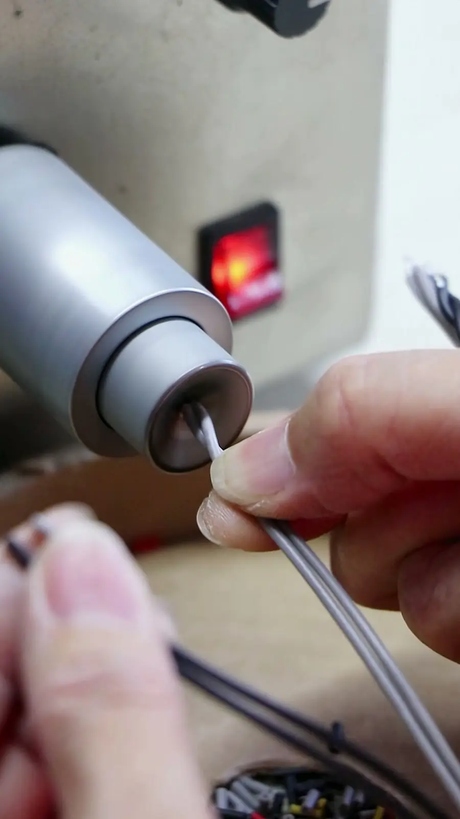
- Strand nicking: Damaged or severed conductor strands during stripping reduce effective cross-section. The crimp may hold during a fast continuity check but fail at moderate axial force because the conductor can no longer carry the expected tensile load.
- Wrong terminal barrel size: A crimp terminal specified for a larger AWG range may not form a tight mechanical bond when applied to a smaller conductor. The result can pass a loosely controlled pull test but open under thermal cycling or vibration.
- Borrowed pass/fail values: Copying one generic force number from another AWG row creates false confidence. Each AWG and barrel combination has its own tensile strength boundary, and a mixed-lot harness cannot be qualified against a single value.
Failure location gives process direction. A wire break outside the crimp suggests conductor damage such as strand nicking. Wire pull-out from the barrel suggests insufficient crimp depth or a terminal barrel that is too large for the AWG. Contact retention failure at the terminal interface points to connector or terminal selection, insertion damage, or incorrect retention features, not only the wire crimp.
How Should You Handle a Borderline Pull Force Result at Receiving Inspection?
A borderline result is not resolved by averaging it with passing pulls. The correct escalation is to increase the sample size for the same AWG and terminal combination and re-test using the exact documented setup. Record failure location on every sample. If borderline readings cluster on one AWG or barrel size, return to crimp height analysis and barrel inspection before accepting the lot.
Require supplier evidence: the exact terminal manufacturer’s published minimum, the crimp tool and die used, and the conductor brush configuration—not a generic internal limit. Final disposition is accept only when all re-test readings meet the AWG-specific minimum and failure mode remains controlled. Otherwise, quarantine, reject, or open a corrective action.
How Do You Challenge a Supplier’s Pass/Fail Criteria Before Accepting the Batch?
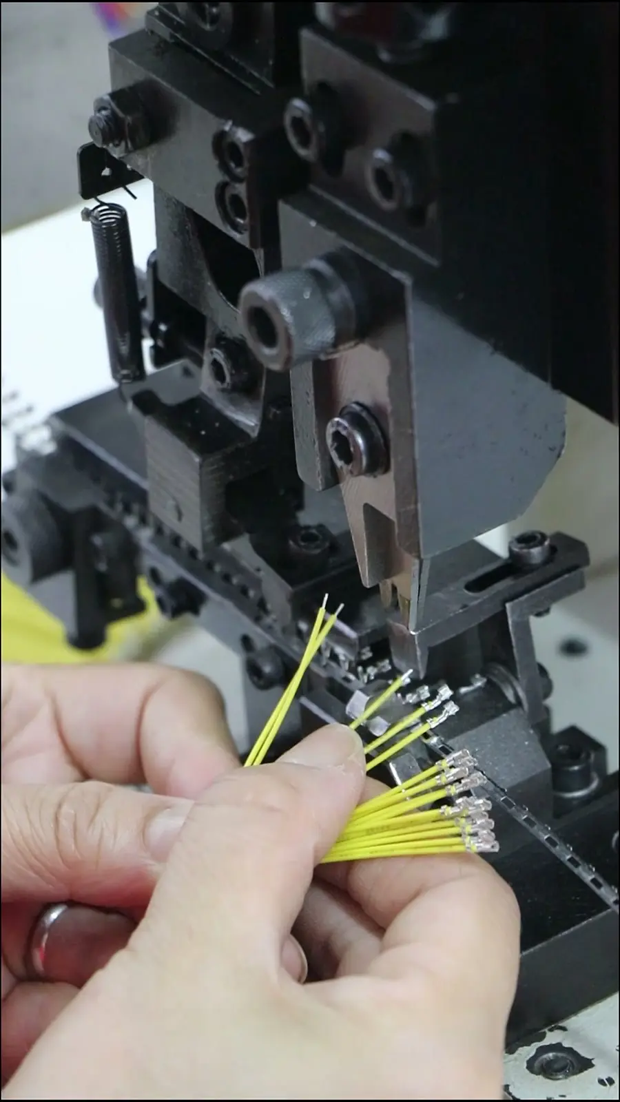
Before lot acceptance, ask for the terminal part number and maker, AWG-specific pull force minimum, barrel size, insulation support presence, crimp tool and die identification, and the referenced standard. An IPC/WHMA-A-620-aligned minimum tensile requirement points back to terminal manufacturer data. An unverified internal limit may have been copied from another AWG row, particularly when a single value spans multiple gauges.
- Terminal maker and part number
- AWG-specific minimum pull force for the barrel size
- Insulation support presence and design
- Crimp tool, die, and conductor brush identification
- Sample pull force reports with failure location and photos
For OEM buyers of custom cable assembly lots, this evidence request should be part of the supplier quality file before incoming inspection closes. A pass/fail summary without failure location or terminal maker data does not support a mechanical-integrity decision.
Suppliers such as EDOM Electronics support OEM buyers with requirement review, connector matching, sample coordination, production follow-up, inspection, and export-ready packaging for custom cable assemblies and wire harnesses. In practice, that support is most useful when the buyer asks for the same AWG-specific data described above, not a single rollup value.
What Does a Closed-Loop Crimp Pull Force Verification Plan Look Like for OEM Incoming Inspection?
The closed loop follows six steps: verify the terminal maker’s AWG-specific minimum; apply the go/no-go checklist; choose crimp height inspection or destructive pull testing based on risk; run a controlled pull force tester setup; record measured force and failure location; and challenge any borderline result or supplier pass/fail value that does not trace to the correct AWG row.
Continuity alone cannot certify mechanical integrity; crimp pull force verification is the missing control at receiving inspection. For a quality engineer holding the original failure report, the immediate action plan is to segregate suspect lots, re-test by AWG and terminal barrel, require supplier data, and update the incoming inspection checklist with the recorded acceptance row.
This practice belongs inside any wire harness manufacturing program that ships to OEM production, as well as in export-focused incoming inspection before release to stock or shipment.
Frequently Asked Questions
What pull force standard applies to crimped wire harnesses?
IPC/WHMA-A-620 is the acceptance standard for cable and wire harness assemblies. It directs the reviewer to the terminal manufacturer’s published minimum tensile value for the specific AWG size and barrel design. UL 486A and IEC 60352-2 provide connection-level context for terminations, but they are not substitutes for terminal maker data.
Can a crimp pass continuity and still fail mechanically?
Yes. An under-crimped junction can maintain strand contact at zero load but open under vibration, thermal cycling, or axial pull. Continuity is an electrical check; crimp pull force verifies mechanical retention of the conductor inside the crimp terminal barrel.
When is destructive pull testing required instead of crimp height inspection?
Destructive pull testing should be used when under-crimp is suspected, when mixed AWG sizes share a single generic pass/fail value, when contact retention under load must be proven, or when a new terminal, tool, or die is qualified. Crimp height inspection is suitable for ongoing process control only after the pull force baseline for that AWG and terminal combination is confirmed.
How should a borderline pull force result be handled?
Do not average a borderline reading with passing pulls. Increase the sample size for the same AWG and terminal combination, repeat the test with the same documented setup, and record failure location. If results cluster on one gauge or barrel size, inspect crimp height and terminal barrel. Accept only if all re-tests meet the AWG-specific minimum.
What evidence should a supplier provide to support pull force pass/fail criteria?
A supplier should provide the terminal part number and maker, AWG-specific pull force minimum, barrel size, insulation support presence, crimp tool and die identification, referenced standard, and sample pull force reports with failure location and photos rather than a pass/fail summary. Suppliers such as EDOM Electronics can coordinate this documentation for OEM custom cable assembly and wire harness lots.
Key Takeaways
- Pull force acceptance must be AWG-specific and terminal-specific, sourced from the terminal manufacturer’s published minimum—not a generic harness-level number.
- Continuity testing cannot certify mechanical integrity; destructive pull testing verifies that a crimp terminal retains the conductor under load.
- Use the Go/No-Go checklist at incoming inspection and record pull speed, barrel size, insulation support, measured force, and failure location on every tested sample.
- Treat borderline results as escalation triggers: increase sample size and verify the same AWG and terminal combination, never average with passing pulls.
- Challenge supplier pass/fail criteria by requesting terminal maker data, tooling records, and sample reports with failure photos before accepting a batch.
For more detail on how receiving and pre-shipment checks fit the export flow, learn more about quality inspection and export packaging support for cable assemblies and wire harnesses.