If your cable assembly inspection ends when the continuity tester shows green, you’re catching open circuits and short circuits — but not the two failure modes that cause most field returns.
Direct answer: A cable tester is an instrument or equipment set used to verify electrical wiring configuration, continuity, insulation integrity, and in some cases mechanical termination quality in cable assemblies and wire harnesses. Basic continuity testing confirms that current can flow from point to point; it does not by itself prove that a crimp will survive vibration or that insulation can withstand voltage stress.
At a Glance
A cable tester is a family of instruments rather than a single device. A continuity tester checks whether the right conductor is connected to the right terminal. A wire map confirms pinout order. An insulation resistance tester measures high-resistance leakage, and a hipot tester applies high voltage to stress insulation. For OEM incoming inspection, a complete acceptance sequence typically includes visual inspection, continuity and pinout verification, crimp pull force testing, and hipot testing — not continuity alone.
What Is a Cable Tester and Where Does It Fit in Incoming Inspection?
A cable tester is not one device but a family of instruments used at different stages of cable and wire harness acceptance. A continuity tester verifies point-to-point current paths. A wire map tester confirms the exact pinout order against a drawing or sample. An insulation resistance tester measures high-resistance leakage between conductors or between a conductor and ground. A hipot tester applies a specified high voltage to stress insulation and expose dielectric weaknesses.
In an incoming inspection workflow, the tester is the gate between supplier production and the buyer’s production line. It converts a drawing, sample, or pinout requirement into a pass/fail record. Basic continuity testing answers the question: is the right wire connected to the right terminal? It does not answer two other questions: is the crimp mechanically sound, and can the insulation survive voltage stress?
A multimeter can spot-check single conductors, but it is too slow and error-prone for multi-conductor harness acceptance.
Why Continuity Testing Is Necessary but Not Sufficient
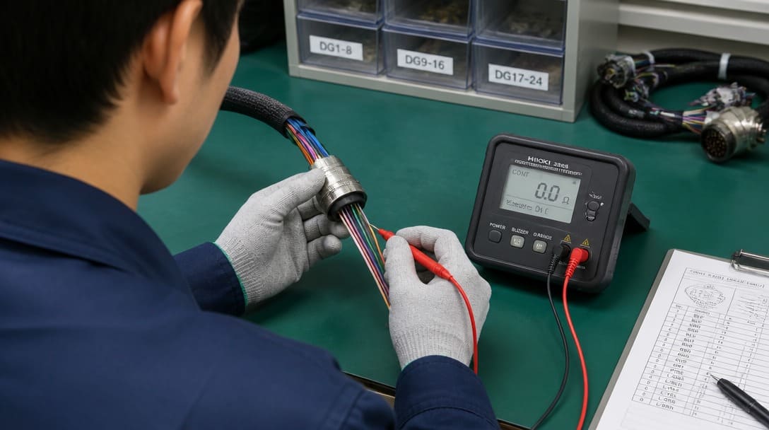
A continuity tester catches an open circuit, where no current path exists, and a short circuit, where an unintended current path exists between conductors. It does this against the expected pinout. If a harness has 12 positions and the tester confirms the correct 12 paths with no cross-connections, the wire map is valid.
What continuity testing misses matters more in the field. A continuity tester does not detect crimp retention force, insulation nicks, dielectric breakdown, fragile strands, or partial conductor damage that still passes a low-current check. A wire map display can show correct continuity and still hide a terminal that will disengage under vibration or temperature cycling.
For many OEM buyers, “light turns green” is the entire acceptance criterion. That is a sampling blind spot, not a complete electrical test. It confirms that the cable is wired correctly at the moment of the test. It does not confirm that the cable is mechanically or electrically safe under operating conditions.
Failure Mode 1: Crimp Integrity and Why It Passes Continuity
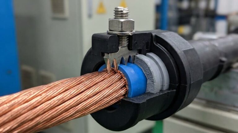
A crimp can electrically connect at the moment of test but have insufficient conductor barrel grip. Continuity confirms a path; it does not confirm mechanical retention. The crimp may remain in contact long enough to pass a low-current signal, then become intermittent under vibration, thermal expansion, or repeated mating and unmating cycles.
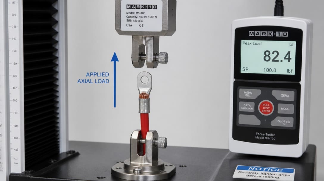
Field failure often appears long after incoming inspection has passed the assembly. This is why crimp verification is a defined process step in structured wire harness manufacturing. Pull force testing applies a controlled axial load to the crimped terminal and is the only reliable acceptance check for crimp retention strength.Note that because pull force testing is a destructive test, it is implemented as part of lot-based destructive sample testing (AQL sampling) rather than 100% full inspection.
IPC/WHMA-A-620[1], the acceptance standard for cable and wire harness assemblies, defines crimp pull force requirements by wire gauge and terminal type. Passing a continuity test does not demonstrate compliance with those mechanical criteria. The standard exists precisely because electrical continuity alone cannot validate a termination.
Test Coverage Table: Continuity vs. Pull Force vs. Hi-Pot
A complete cable tester setup covers three main areas: continuity for correct wiring, pull force for crimp strength, and hipot for insulation integrity.For a detailed breakdown of exactly what each test catches and misses, see our guide on What Does a Cable Tester Do.
Compare your current incoming inspection checklist against this table. If pull force and hi-pot are optional, the two highest-risk failure modes are not being verified. Manufacturers that standardize these checks consistently reject fewer lots in the field; see how manufacturers ensure consistent cable assembly quality.
Pull Force Testing: Making Crimp Verification Standard
A pull force tester uses a calibrated gauge to pull the wire from the terminal until failure. The recorded force must meet IPC/WHMA-A-620 minimums for the wire gauge and terminal design. Failures include wire pull-out, terminal unwrap, conductor strand breakage, or insulation barrel slip. Each indicates a process control issue in cutting, stripping, or crimping. The recorded force must meet IPC/WHMA-A-620 minimums for the wire gauge and terminal design. For gauge-specific tensile thresholds and acceptance rules across different conductor sizes, see our detailed guide on crimp pull force test AWG standards.
A bench multimeter cannot duplicate the controlled load of a pull force fixture. The multimeter measures electrical potential, resistance, or current; it does not apply a destructive axial load to verify mechanical retention.
We made pull force testing and hi-pot standard on every outgoing shipment — not because customers always ask for it, but because the failure modes that cause field returns are exactly the ones continuity testing cannot catch.
Hi-Pot Testing: Catching Insulation Breakdown Before the Field Incident
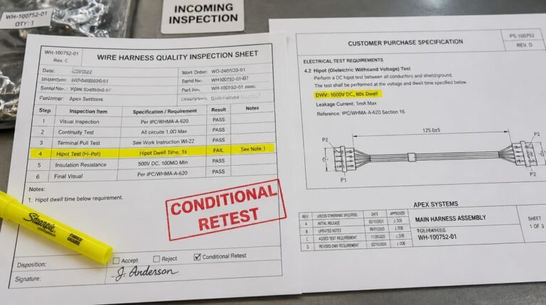
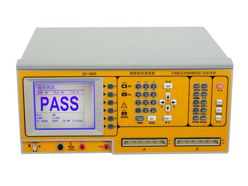
A hipot tester applies a specified high voltage between conductors and between conductors and shield or ground. The purpose is to verify that the insulation can withstand transient overvoltage and environmental stress. Insulation breakdown often starts as a microscopic cut in the jacket, a pinched wire during assembly, or contamination in the connector. None of these conditions create a continuity failure at low voltage.
An insulation resistance tester measures megohm-level leakage at a lower test voltage. It is often used as a pretest or for trending insulation health over time. The hipot test is the stress test that catches gross dielectric weakness before a cable reaches the field. For a deeper inspection sequence, see how to test high voltage cables. To evaluate whether a supplier’s reported dwell time and parameters meet incoming acceptance standards, refer to our detailed guide on hipot testing duration requirements for cable assemblies and how long an insulation resistance test should take to verify charging and absorption currents have fully settled.
Building a Practical Cable Assembly Test Plan for Incoming Inspection
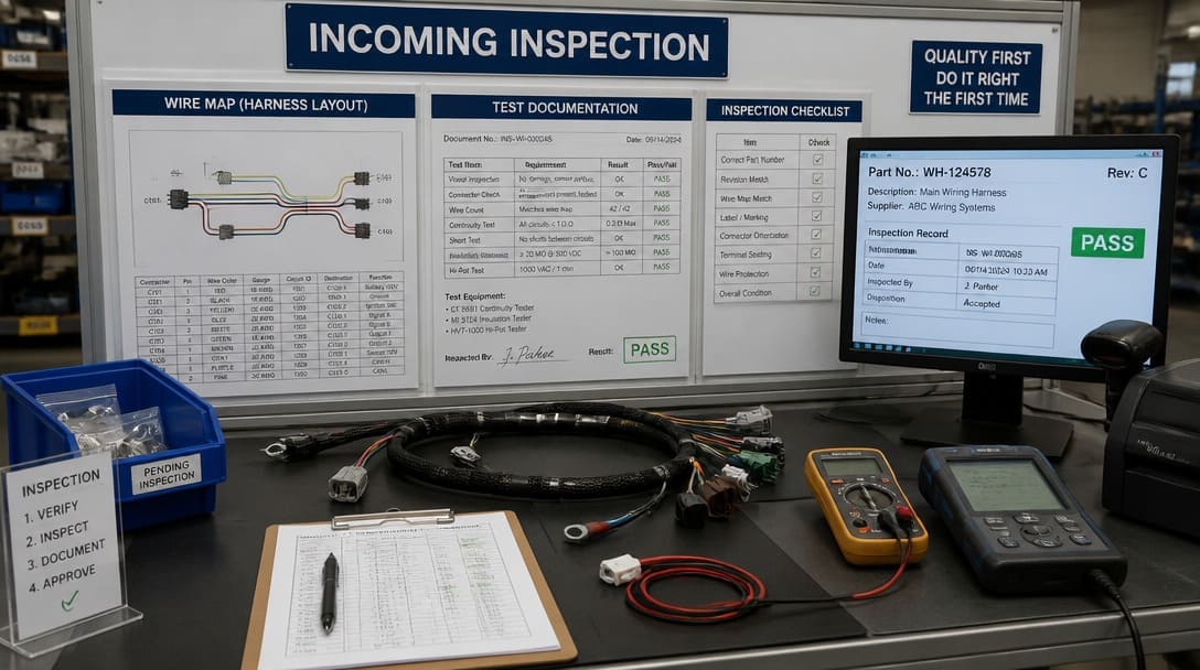
Define acceptance criteria from IPC/WHMA-A-620, including continuity pinout, crimp pull force, and hipot test voltage and dwell for the cable class. For custom cable assembly projects with unique pinouts or jacket materials, the test plan should be developed alongside the custom cable assembly specification, not after production.
Sequence matters. Start with visual and wire map verification, then continuity, then pull force on crimped samples, then hipot on the finished assembly. Document each result against the lot, sample size, and AQL. This creates incoming inspection records that can be shared with the supplier during nonconformance review.
| Step | Test or check | Tool or method | Acceptance criterion |
|---|---|---|---|
| 1 | Visual inspection | Drawing, sample, magnification | No crushed connectors, no exposed conductors, labels legible |
| 2 | Pinout and wire map | Continuity tester or wire map tester | Matches drawing or approved sample for every conductor |
| 3 | Crimp retention | Pull force tester | Meets IPC/WHMA-A-620 minimum for wire gauge and terminal type |
| 4 | Dielectric strength | Insulation resistance tester, then hipot tester | No breakdown or excessive leakage at specified voltage and dwell |
| 5 | Documentation & Test Reports | Supplier COA, Hi-Pot test logs, and lot traceability | 100% test reports provided per shipment; raw data matches AQL sampling standards for destructive mechanical tests. |
Use a multimeter only for spot checks within the plan, not as a replacement for automated continuity or hipot testing. Adapt test methods to cable type. Oil-resistant cables may require additional jacket verification — see how oil resistant cables are tested for quality.
Final Verification and Export Packaging: Closing the Loop
Final verification before shipment should confirm that test records, labels, and packaging match the lot, so the receiving inspection does not inherit an untraceable batch. Cable assembly quality is not only electrical. Crushed connectors, bent terminals, and inadequate export packaging can create field failures that no cable tester will catch.
Suppliers such as EDOM Electronics support OEM buyers with requirement review, connector matching, sample coordination, production follow-up, inspection, and export-ready packaging for custom cable assemblies and wire harnesses. This closing step connects the test bench to the dock door. Quality inspection and export packaging should not be treated as separate from the electrical test plan.
Frequently Asked Questions
What is the difference between a continuity tester and a hipot tester?
A continuity tester checks whether current can flow along an intended path and detects open circuits and short circuits. A hipot tester applies high voltage between conductors and ground or shield to verify insulation can withstand voltage stress. Continuity testing does not catch insulation defects.
Can a multimeter replace a cable tester?
A multimeter is useful for spot-checking individual conductors, but it is too slow and error-prone for multi-conductor harness acceptance. It also cannot perform automated pinout mapping, controlled pull force testing, or hipot stress testing.
Why do crimped terminals pass continuity but fail in the field?
A crimp can conduct current at the moment of test without having adequate mechanical retention. Under vibration, temperature cycling, or mating cycles, the weakened crimp can become an intermittent open. Pull force testing is required to verify crimp retention.
When should a cable assembly fail hipot testing?
A hipot failure occurs when insulation breaks down or leakage current exceeds the specified limit at the test voltage. Common causes include nicked insulation, contamination, insufficient clearance or creepage, and damaged sleeving.
What standard defines cable assembly acceptance criteria?
IPC/WHMA-A-620 is the acceptance standard for cable and wire harness assemblies. It defines workmanship classes and acceptance requirements for continuity, crimp pull force, insulation, and other production criteria.
Key Takeaways
- A cable tester is not a single device; it includes continuity testers, wire map testers, insulation resistance testers, and hipot testers.
- Continuity testing confirms correct wiring but misses crimp integrity and insulation breakdown.
- Pull force testing is the only reliable acceptance check for crimp retention strength, with criteria defined by IPC/WHMA-A-620.
- Hi-pot testing catches dielectric weaknesses that are invisible in low-voltage continuity checks.
- A complete incoming inspection plan sequences visual, pinout, continuity, pull force, and hipot checks with documented traceability.