For OEM buyers in extreme climate regions like Minnesota, ensuring custom RF cables survive harsh winters requires more than just calling out a connector and a length. While many Midwestern OEMs default to local fabrication, partnering with an advanced offshore manufacturer like EDOM Electronics can deliver superior RF precision, full VNA testing, and scalable pricing without sacrificing lead times.
Key Takeaway: Successful coaxial cable fabrication requires specifying more than mechanical dimensions—it’s an RF precision task. Without defining frequency range, impedance tolerance, shielding effectiveness, and environmental conditions, even a mechanically perfect cable can cause signal integrity failures.
The RF Imperative: What Your Coaxial Cable Specification Is Missing
Most drawings that arrive at a fabrication desk list a connector part number and a cable length, and assume the job is done. That mechanical completeness masks a dangerous gap: a coaxial cable is not a wire—it is a transmission line. Every dimension, material interface, and termination detail affects its characteristic impedance, return loss, and shielding integrity. When an OEM buyer treats the assembly as a commodity cut-and-crimp operation, the result is a cable that may look right on a bench but introduces signal degradation the moment it’s installed in the field.
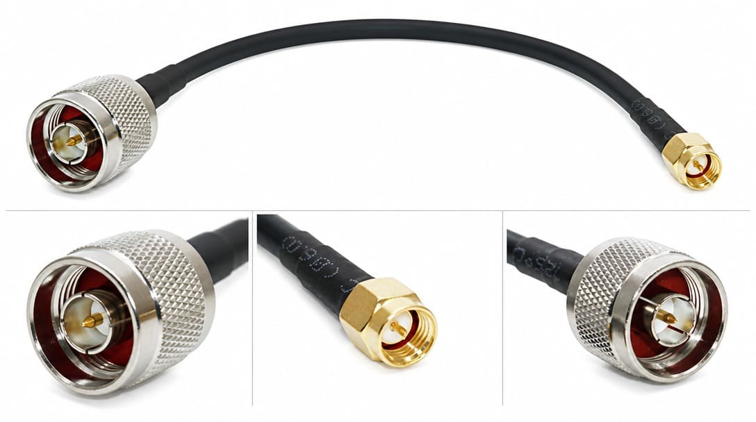
While many Midwestern OEMs initially seek local fabrication to ensure quality control, true RF performance depends on stringent testing protocols, not geography. A global manufacturing partner equipped with advanced Vector Network Analyzers (VNA) and automated stripping equipment can often deliver higher precision at scale. A fabricator who merely builds to a mechanical drawing without probing the RF requirements is missing the entire purpose of the cable. The following sections outline the specification framework and fabrication pitfalls that separate a reliable RF assembly from a costly field return.
The Specification Checklist: What Every OEM Buyer Must Define Before Ordering Coaxial Cables
Before a single connector is crimped, the procurement and engineering teams should align on a disciplined set of parameters. The table below translates vague requirements into a concrete checklist that any qualified fabricator should request—and that any serious OEM should provide.
| Parameter | What to Specify | Why It Matters for RF Integrity and Field Survival |
|---|---|---|
| Operating Frequency Range | Minimum to maximum frequency in GHz or MHz | Determines connector precision grade, cable construction, and acceptable impedance discontinuities. A cable that performs well at 900 MHz may fail return loss at 6 GHz. |
| Characteristic Impedance | 50 Ω or 75 Ω, with tolerance (e.g., ±3 Ω) | Mismatch creates reflections. The tolerance band dictates how tightly dielectric diameter and pin alignment must be controlled. |
| Attenuation Budget | Maximum insertion loss in dB at a specified frequency and length | Derates system link budget. Requires correct dielectric material (solid PE, foam PE, PTFE) and accurate assembly. |
| VSWR / Return Loss Limits | Maximum VSWR or minimum return loss (dB) across the band | Directly penalized by dielectric trims, connector seating planes, and solder voids. A 0.5 mm trim error can move a reflection peak into the operating band. |
| Shielding Type & Effectiveness | Foil, braid coverage percentage, or combination; attenuation in dB | Dictates EMI immunity and emissions. Low coverage at the termination point is a primary source of radiated susceptibility. |
| Environmental Conditions | Temperature extremes, moisture, UV exposure, freeze-thaw cycles, chemical exposure | Selects jacket material, seal boots, and corrosion-resistant platings. Minnesota winters demand low-temperature flexibility and hydrolysis-resistant compounds. |
| Mechanical Constraints | Minimum bend radius, planned flex cycles, vibration profile | Prevents center conductor migration, braid fatigue, and jacket cracking. Required for dynamic applications. |
| Connector Precision | Center conductor protrusion, pin depth, torque value, mating cycle life | A 0.2 mm deviation in center contact position can create an impedance bump that fails VSWR at high frequencies. |
| Applicable Standards | IPC/WHMA-A-620[1] Class 2 or 3 for RF cable assemblies, UL flammability rating, RoHS, REACH | Defines acceptance criteria for workmanship and materials. Class 3 mandates tighter inspection and documentation, essential for mission-critical RF links. |
| Military & High-Reliability Standards | MIL-DTL-17 (Coaxial Cables), MIL-PRF-39012 (RF Connectors) | Mandatory for defense, aerospace, and harsh-environment ruggedized radio links requiring extreme phase stability and shielding effectiveness. |
If your current fabrication partner doesn’t ask for these parameters, consider it a red flag. A partner who only requests connector part numbers and length isn’t performing RF fabrication—they’re just crimping cables. Engaging a fabrication partner that probes these parameters before providing a quote signals a focus on RF integrity rather than just assembly speed. For OEM buyers who supply similar diligence to wire harness specifications, the same principle applies: wire harness manufacturing success depends on clear routing, labeling, and inspection criteria, not just a bill of materials.
Five Field Failure Modes That Start at the Fabrication Bench
If your current fabrication partner doesn’t ask for these parameters, consider it a red flag. A partner who only requests connector part numbers and length isn’t performing RF fabrication—they’re just assembling cables without the rigorous quality control that ensures consistent cable assembly quality.
- Impedance discontinuities from imprecise dielectric trimming or connector misalignment. When the dielectric is trimmed too short or the connector body is seated at an angle, the local impedance changes sharply. Above 6 GHz, this creates a return loss failure that bench-level continuity testing never catches.
- Shield termination flaws. A pigtail drain wire connection instead of a 360° peripheral termination creates an inductive stub that undermines shielding effectiveness. EMI susceptibility increases, and intermodulation products can appear in multichannel systems.
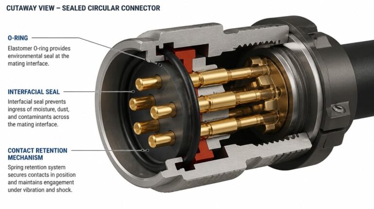
- Moisture ingress through inadequate sealing. Without a proper environmental boot or O-ring, condensation migrates into the connector-cable junction. Corrosion progresses over months, eventually causing intermittent opens or a complete loss of signal.
- Cold-weather jacket cracking. Standard PVC formulations become brittle below freezing. In a climate like Minnesota’s, repeated freeze-thaw cycles accelerate cracking, exposing the shield and dielectric to moisture and sunlight.
- Conductor pull-out under vibration and dielectric melting during soldering. Solder reflow into the braid or excessive heat that distorts the dielectric core moves the impedance reference plane. Field vibration then works the center contact loose, raising resistance until the link fails.
Each of these failures is preventable when the fabrication process follows the inspection points detailed in relevant standards. Ultrasonic cleaning of flux residues, controlled strip tools, and go/no-go gauges for center contact position are not optional—they are table stakes for any RF assembly.
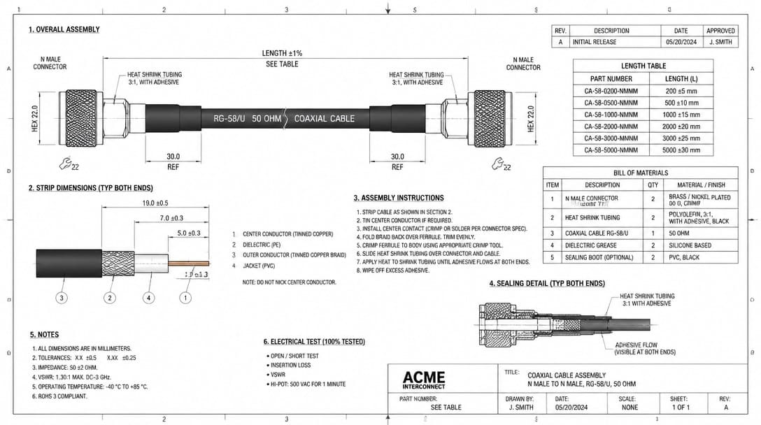
From 2D Print to RF-Ready Assembly: Drawing Details That Prevent Redesign
It’s not uncommon to receive prints that list the connector series and cable part number, but nothing about the seating plane or how far the center conductor protrudes. When the cable is meant for a 6 GHz system, that protrusion changes the impedance bump enough to fail return loss requirements. To avoid iterative sampling and field retrofits, every coaxial cable fabrication drawing should include the following:
- Strip dimensions with tolerances for inner conductor, dielectric, and outer jacket, directly from the connector manufacturer’s termination instructions.
- Over-mold or boot specification, including material durometer and sealing interface.
- Environmental seal type and location—critical for outdoor or washdown applications.
- Connector torque values for both the coupling nut and the termination ferrule.
- Required test reports: at a minimum, a VNA S-parameter plot (S11 and S21) across the operating band, and for jacketed assemblies that carry voltage, a withstand voltage test record per applicable UL requirements.
- Marking and labeling scheme for traceability.
Soldered terminations demand the same care. IPC J-STD-001 defines acceptability criteria for soldered electrical connections, and a fabricator unfamiliar with its requirements risks cold joints or heat-damaged dielectrics that shift the impedance profile. Requesting sample assemblies with full test data before releasing a production run is the most effective way to validate that what appears on the print actually translates into an RF-performing cable.
Shielding Integrity: Why the 360-Degree Rule Is Non-Negotiable
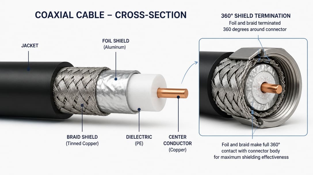
Shielding is not simply a layer of braid—it is a continuous conductive envelope that must maintain its integrity through the connector termination. For frequencies below a few hundred megahertz, a high-coverage braid (90% or greater) may suffice. As frequency rises or EMI immunity requirements tighten, a foil-plus-braid combination provides the necessary coverage while remaining flexible. But the choice of cable shield is meaningless if the termination method breaks the envelope.
The physics is straightforward: any gap in the 360-degree shield termination creates a slot antenna. A crimp ferrule that compresses the braid uniformly around the connector body maintains the current path. A pigtail drain wire, even when perfectly soldered, introduces series inductance. At frequencies above 1 GHz, this inductive stub introduces parasitics that can severely degrade shielding effectiveness—in our lab tests, poorly terminated pigtails often exhibit a 10 to 20 dB loss in shielding performance compared to a 360-degree full peripheral termination—significantly increasing EMI susceptibility. For sensitive outdoor installations—such as a fixed wireless antenna link—that degradation invites intermodulation interference from nearby transmitters and accelerates corrosion at the exposed drain joint.
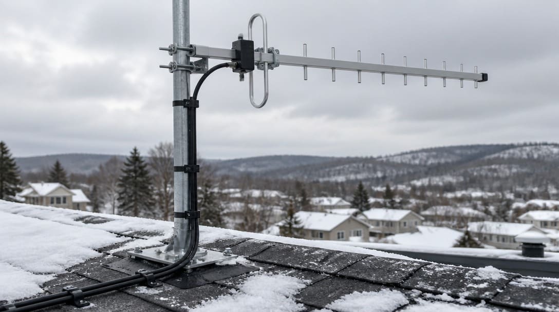
In our experience supplying agricultural automation OEMs in the upper Midwest, environmental oversights are costly. In one instance (prior to our engagement), a client specified a standard PVC jacket and a simple braid cable with a pigtail drain for an outdoor antenna. After a single Minnesota winter of severe freeze-thaw cycles (-20°F to 40°F in weeks), moisture migrated along the drain wire into the connector body, causing total signal failure. By upgrading to a UV-resistant PUR jacket and a 360-degree crimp ferrule with environmental boots, we eliminated this failure mode entirely.
How Minnesota’s Winters Expose Fabrication Weaknesses
For Midwest OEMs, mitigating extreme climate stress is a primary concern. Temperature swings from -30°F to 90°F, repeated freeze-thaw cycles, and intense summer UV radiation place extraordinary stress on cable materials. Specifying cold-weather rated compounds—such as UV-stabilized Polyurethane (PUR) or specialized PTFE rated for -40°C flexibility—is critical. Jacket compounds that remain flexible in a California warehouse turn brittle on a Minnesota rooftop in January.
The hidden cost of environmental corner-cutting becomes clear in the case described above: a roof antenna feeder designed with standard connectors and no cold-weather sealing suffered jacket cracks and water ingress during freeze-thaw cycles. Within months, signal degradation led to system downtime and costly field replacements. For OEM buyers, investing in waterproof cable assembly manufacturing can prevent such failures.
Material selection must therefore consider more than flammability. UL approvals confirm that a jacket compound meets certain fire performance requirements, but a Minnesota installation also demands a cold-bend test result that proves flexibility at the lowest expected temperature. For OEMs exporting products to Europe, REACH compliance verifies that no restricted chemicals are present in the plastics or platings. And for global shipments, RoHS compliance is a baseline requirement. A fabrication partner who understands these regional and regulatory demands will proactively propose materials and processes rather than waiting for the buyer to specify every compound by grade number.
The Cost of an Impedance Bump: Why ‘Cheap’ Custom Cables Become Expensive Field Returns
Procurement teams naturally compare unit prices, but the total cost of ownership for a coaxial cable assembly is dominated by what happens after installation. A $12 assembly built strictly to mechanical dimensions may pass a continuity test but generate ghost VSWR failures that trigger field technician visits, system downtime, and engineering investigations. A $15 assembly verified against the specification checklist—with a VNA plot showing compliant return loss, a documented 360° shield termination, and cold-weather jacket testing—pays for itself the first time a Minnesota winter does not take the link offline.
The hidden costs ripple outward: shipping replacement cables, rework logistics, service team overtime, and brand reputation erosion when a customer’s system fails repeatedly. Procurement managers who evaluate fabrication partners only on unit price are externalizing those costs onto the OEM’s operations. A disciplined partner provides the test data that allows the buying team to predict field performance, lowering the total lifecycle cost even when the piece price is slightly higher.
Overcoming the Distance: Sourcing High-Spec RF Cables Globally
OEM buyers often worry about quality control when manufacturing outside their home state. To mitigate risk, ensure your global manufacturing partner provides:
- Pre-shipment VNA Testing: Every critical RF assembly batch should include S11 (Return Loss) and S21 (Insertion Loss) plots.
- Material Verification: Certifications for cold-weather compliant compounds (e.g., specific PUR or PTFE grades).
- Transparent Logistics & Quick Turnaround : We bridge the geographic gap with direct air-freight (DHL/FedEx) delivering from our Shenzhen facility to Minnesota in 5-7 business days.
- Prototyping & MOQ : We support quick-turn prototyping (typically 1-2 weeks, starting from as low as 10-50 pieces) for engineering validation, smoothly scaling to volume production of 10,000+ units. to validate the RF performance in your actual system before committing to volume production.
- Traceability & RMA : Every batch is serialized and tied to its specific VNA test log. In the rare event of a defect, our root-cause analysis is data-driven, not guesswork.
From Search to Shipment: Your Next Steps for Coaxial Cable Fabrication
The journey from a web search for “coaxial cable fabrication Minnesota” to a production-ready RF assembly starts with a disciplined specification and ends with a validated product. Recap the five steps:
- Define the full RF and environmental checklist before releasing an RFQ.
- Anticipate failure modes—impedance bumps, shield gaps, moisture paths—and build prevention into the drawing and inspection plan.
- Detail the drawing with strip dimensions, sealing, torque values, and required test reports.
- Enforce the 360-degree shielding rule at every termination, and select jacket materials that survive the installation climate.
- Compare fabrication partners based on the questions they ask, not just the speed of their quote.
A partner that also offers thorough quality inspection and export packaging ensures that validated assemblies arrive on your dock in the same condition they left the test bench. For OEM teams ready to move from a local search to a production-grade partner, a supplier like EDOM Electronics provides the engineering review, connector matching, and testing documentation that transforms a 2D print into an RF-validated assembly. Explore custom cable assembly solutions designed to meet full RF and environmental specifications, not just mechanical fit.
Frequently Asked Questions
What is the difference between 50 Ω and 75 Ω coaxial cable?
50 Ω cables are standard for RF and microwave systems, offering a balance between power handling and low attenuation. 75 Ω cables are used primarily in video and telecommunications applications where lower attenuation per unit length is prioritized. Using a 75 Ω connector on a 50 Ω system creates an impedance mismatch that produces return loss and signal degradation, so the entire assembly—cable and connectors—must share the same design impedance.
Why is 360-degree shielding termination so important?
A 360-degree peripheral termination maintains a continuous conductive path around the full circumference of the cable shield, preventing gaps that act as slot antennas. Any break in that continuity, such as a pigtail drain wire, lets RF energy enter or escape, reducing shielding effectiveness and making the assembly susceptible to EMI and intermodulation interference.
How does cold weather affect coaxial cable assemblies?
Repeated freeze-thaw cycles can cause standard PVC jacket materials to become brittle and crack, exposing the shield and dielectric to moisture. Low temperatures also change the flexibility of the cable, potentially exceeding minimum bend radius and damaging the internal geometry. Connectors without environmental sealing can draw in moisture through capillary action, leading to corrosion and intermittent signal failures.
What standards apply to coaxial cable fabrication?
The primary workmanship standard is IPC/WHMA-A-620, which includes a section dedicated to RF cable assemblies. For soldered connections, IPC J-STD-001 defines acceptability requirements. Additionally, UL ratings address fire safety, RoHS restricts hazardous substances in electronic equipment, and REACH regulates chemicals in products sold in the European Union. The applicable class (2 or 3) depends on the end-use criticality.
How can I verify fabrication quality if I don’t own a network analyzer?
Request that the fabricator supply test reports generated during final inspection. A typical report set for an RF cable assembly includes a calibrated VNA trace showing S11 (return loss) and S21 (insertion loss) over the full frequency range of interest, along with a continuity and isolation check. These reports allow your engineering team to validate performance without requiring in-house test equipment.
Key Takeaways
- Coaxial cable fabrication is not a commodity crimping task—it demands full RF specification of frequency, impedance, attenuation, VSWR, shielding, and environment.
- A fabrication drawing that omits strip dimensions, connector protrusion, and sealing details will almost certainly lead to costly redesign cycles and field failures.
- The 360-degree shielding termination rule is non-negotiable for maintaining signal integrity and preventing corrosion in outdoor and harsh environments.
- Minnesota’s winter conditions accelerate material failures that remain hidden in milder climates; material selection must account for cold flexibility, UV resistance, and moisture sealing.
- Evaluating total cost of ownership—not just unit price—steers OEMs toward fabrication partners that provide RF test data and long-term reliability.