A JST connector is a board-to-wire or wire-to-wire connector(see What Is a Connector? A Practical Overview for OEM Buyers) manufactured by JST Mfg. Co., Ltd. and identified by series, pitch, circuit count, termination style, and mating half, used for signal and low- to medium-current interconnects in OEM equipment.
When a BOM Line Says “JST Connector” and Nothing Else
In a sourcing review, a new control board BOM arrives from the design group with one line reading “JST connector.” The procurement manager must decide whether to quote it, while the engineer next to them asks whether a 2.50 mm pitch JST XH will actually fit a PCB footprint drawn for 2.54 mm headers. Both questions stall before they start because the series, pitch, termination style, circuit count, and mating half are not itemized on the drawing.
The buyer’s explicit question is: “Can I quote this without knowing the series, pitch, and mating half?” The engineer’s explicit question is: “Will a 2.50 mm XH fit a 2.54 mm header layout, or do we need a new board layout?” The answer to the first is no. A quote based on “JST connector” is not a quote; it is a placeholder. The answer to the second is usually no. A 2.50 mm pitch and a 2.54 mm pitch may look close on a two-pin board, but at higher pin counts the accumulated misalignment prevents reliable mating and can damage contacts.
The remainder of this article moves through the decision sequence: identify the series first, then verify pinout and mating-part pairing before quoting.
What “JST Connector” Actually Means—and What It Doesn’t
JST is the manufacturer name, not a part number, pinout, or footprint. A BOM line that says only “JST connector” is functionally similar to listing “bolt” without thread pitch, length, material, or head style. The noun identifies a family of crimp-style, wire-to-board interconnect products, but it does not identify a specific component that can be purchased, loaded, or tested.
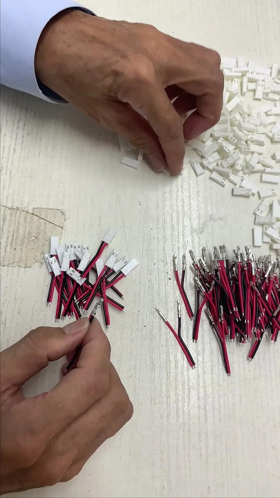
To turn the noun into a part number, the sourcing package needs at least five data points: series, pitch, circuit count, termination style, and the mating half. Wire-to-board describes the application: a crimped wire lead inserted into a housing that mates with a PCB header or through-hole pads. Crimp contact describes how the wire is terminated: the stripped conductor is placed into a metal terminal, the terminal crimp barrel is compressed around the conductor strands, and the terminal is then inserted into a connector housing.
Sourcing Rule: The 5-Point JST BOM Cleansing Formula
A BOM line is sourcing-ready only when all 5 variables are locked:
- Series Code: e.g., XH, PH, ZH, SH, GH (defines mechanical architecture and current rating).
- Centerline Pitch: Exact pin-to-pin distance measured in mm (e.g., 2.50 mm vs. 2.54 mm).
- Circuit Position (Pin Count): Number of active electrical conductors (e.g., 4-pin, 6-pin).
- Termination & Plating: Crimp terminal part number, conductor gauge (AWG), and contact plating (Tin vs. Gold).
- Exact Mating Pair: Full manufacturer part number for both female plug housing and male PCB wafer/shrouded header (straight/top entry vs. right-angle/side entry).
Buyers often use “wire-to-board” and “crimp contact” interchangeably, but they define two distinct aspects: wire-to-board is the interconnect architecture, whereas crimp contact is the termination method. While a given JST series typically employs crimp contacts in a wire-to-board configuration, the compatible wire gauge range and outer insulation diameter remain strictly governed by the specific terminal part number.
Series Identification by Pitch, Termination Style, and Wire Gauge
The first go/no-go decision is to identify the series before considering pinout or mating part. The common series form a cross-check set:
- JST XH (2.50 mm pitch): Rated at 3A AC/DC, 250V; wire range 30 to 22 AWG. Ideal for internal control boards, battery balancing leads, and power distribution sub-assemblies.
- JST PH (2.00 mm pitch): Rated at 2A AC/DC, 100V; wire range 32 to 24 AWG. Compact profile for compact instrumentation, drones, and sensor modules. Not cross-compatible with 2.50 mm XH.
- JST ZH (1.50 mm pitch): Rated at 1A AC/DC, 50V; wire range 32 to 26 AWG. Designed for dense consumer electronics, medical handpieces, and tight LED drivers.
- JST SH (1.00 mm pitch): Rated at 1A AC/DC, 50V; wire range 32 to 28 AWG. Ultra-fine pitch requiring automated crimping presses; common in gimbal wiring and miniature camera modules.
- JST GH (1.25 mm pitch): Rated at 1A AC/DC, 50V; wire range 30 to 26 AWG. Features a positive mechanical locking latch with audible tactile click for high-vibration drone flight controllers and automotive sensors.
Pitch alone is not enough. Termination style, wire gauge range, crimp terminal thickness, and mating face geometry differ by series. A 2.00 mm PH connector does not share the same board footprint as a 2.50 mm XH, and a 1.25 mm GH terminal cannot be crimped with tooling intended for a 1.00 mm SH contact. Wire gauge is part of terminal selection because the crimp contact must match both the stripped conductor size and the insulation diameter; if either dimension is wrong, the terminal may not close cleanly or may not retain the insulation support.
Series identification is therefore the first gate. If the BOM cannot provide the series or the measured pitch, stop and request the missing drawing or sample before quoting.
JST Series Selection / BOM Verification Checklist
The table below is a working cross-check rather than a catalog listing. Use it as a go/no-go tool during drawing review and BOM cleansing.
| Series | Pitch | Application interface | Termination style | Mating / footprint note |
|---|---|---|---|---|
| JST XH | 2.50 mm | Wire-to-board signal and low-current power | Crimp contact | Official JST XH is 2.50 mm only. Pitch error accumulates at 0.04 mm per circuit; do not force-mate onto 2.54 mm (0.1″) PCB headers on circuits > 4 pins. |
| JST PH | 2.00 mm | Wire-to-board compact signal | Crimp contact | Verify PCB pad pitch and mating header series |
| JST ZH | 1.50 mm | Wire-to-board dense signal/LED | Crimp contact | Small wire gauge and tighter pad spacing |
| JST SH | 1.00 mm | Wire-to-board fine-pitch signal | Crimp contact | Fine-pitch pads; terminal and tooling must match |
| JST GH | 1.25 mm | Wire-to-board latch-style signal | Crimp contact | Positive latch; confirm keying and header orientation |
| JST VH | 3.96 mm | Wire-to-board larger conductor / higher current | Crimp contact | Larger contact and housing profile; not drop-in for XH or PH |
| JST EH | 2.50 mm nominal | Wire-to-board larger conductor | Crimp contact | Same nominal pitch as XH but different terminal profile; verify full part number |
Run the following go/no-go questions against every line before quoting:
- Does the BOM pitch match the PCB pad pitch and the measured housing centerline?
- Does the wire gauge fall inside the terminal’s rated range for both conductor and insulation diameter?
- Is the mating half listed as a full manufacturer part number, not just “header” or “housing”?
- Does the selected series match the required keying and latch behavior?
For wire-to-wire applications, confirm that the series has an approved wire-to-wire housing or relay option. Most series in this table are specified as wire-to-board; if the drawing shows two cable-side housings mating together without a PCB header, the series and mating pair need to be re-evaluated before quoting. Similarly, if the BOM lists an IDC termination, a crimp-contact JST series is not automatically compatible—termination style must be kept as a separate check from pitch.
VH and EH are not drop-in replacements for XH or PH. VH uses a 3.96 mm pitch and larger wire-to-board contacts for higher-current runs; EH shares a nominal 2.50 mm centerline with XH but uses a different terminal profile, so a mating half or footprint cannot be validated by pitch alone.
Pinout, Keying, and Mating-Part Pairing Before You Quote
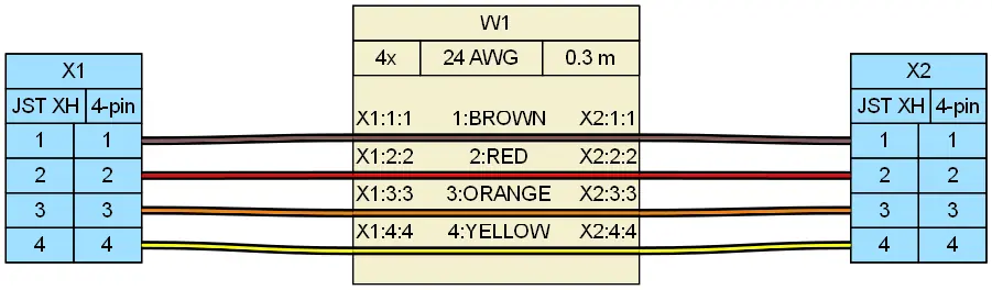
After the series passes the pitch and wire-gauge cross-check, the next gate is pinout and mechanical pairing. Pin 1 marking, silkscreen orientation, and cable routing must match the approved assembly drawing—not just the series name. A JST XH connector can have the correct pitch and still be wired backward if pin 1 is assigned to the wrong side of the housing or if the cable drain direction does not match the enclosure.
Keying and latch differences are common quote blockers. A mating half described only as “housing” or “header” does not tell the supplier whether the latch tab, polarization rib, or keying slot is present. The full manufacturer part number for both connector halves is the minimum required to lock pricing and lead time. Without that, the buyer is quoting a family, not a component.
Pinout and mating-part verification should be treated as the second go/no-go stage: first the series cross-check passes, then the complete pair is confirmed.
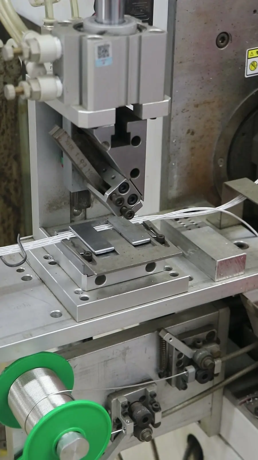
Crimp Workmanship and Pull Force: IPC/WHMA-A-620[1] Acceptance as a Practical Gate
IPC/WHMA-A-620 defines acceptance criteria for wire terminations, including crimp workmanship and pull-force requirements. It is not a quality badge or a connector brand certification; it is a practical acceptance standard that tells the inspector what to look for at the crimp barrel, insulation support, and wire entry area.
For JST crimp contacts, inspection must adhere to IPC/WHMA-A-620 Class 2 or Class 3 acceptance criteria: conductor brush must extend past the front edge of the wire crimp barrel (typically 0.1 mm to 0.5 mm for miniature contacts) without entering the mating zone, and the wire insulation must be securely locked within the insulation crimp barrel without penetrating the conductor crimp zone. Tensile pull-force must be verified using a calibrated pull tester at 25 mm/min to 50 mm/min: standard thresholds require ≥ 11 N (2.5 lbf) for 28 AWG, ≥ 20 N (4.5 lbf) for 26 AWG, and ≥ 36 N (8.0 lbf) for 24 AWG (referencing IPC/WHMA-A-620 Table 19-12). Crimp height (C-height) must be calibrated per terminal applicator specification sheets (typically held within a tight ±0.03 mm tolerance).
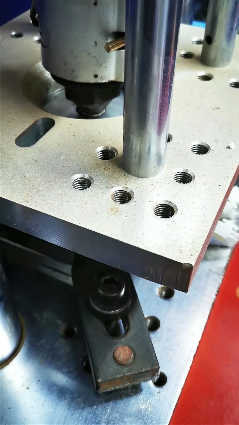
Generic crimp tools are a frequent source of field problems. Terminals from different series and manufacturers are designed around specific die profiles and crimp heights. When a generic tool is used, the result can be a partially closed barrel, cracked terminal arms, or loose strands that do not carry current reliably. During sample confirmation or incoming inspection, pull-force testing serves as a go/no-go gate before production is released.
Field Failure Modes When a JST BOM Line Stays a Noun
The cost of leaving “JST connector” as a noun instead of a full part number appears in prototypes and field returns, not just in delayed quotes.
Pitch accumulation failure. A 2.50 mm XH forced onto a 2.54 mm header layout may appear to mate on a two- or three-position footprint, but the offset accumulates across a 10- or 20-way header until the contact blades no longer line up with the female terminals. The connector may partially latch or close, leaving the assembly to fail under vibration or removal force.
Generic crimp tool damage. Mismatched tooling can crack the terminal barrel, leave the insulation support unsupported, or produce a partial crimp that retains the wire only until the harness is flexed. Intermittent contact under equipment vibration is a typical result.
Tin-on-gold fretting corrosion. When tin-plated terminals are mated with gold-plated headers in thermal cycling or vibration-prone environments, the contact interface can develop fretting corrosion. The series may be correct, but the plating combination and mating environment were never evaluated because the BOM line did not specify plating or the mating half.
Missing mating part numbers. A supplier cannot verify mechanical retention, latch height, or insertion depth from a single connector housing. The quote becomes guesswork, the sample may not reflect the approved layout, and the buyer absorbs rework later in the program.
From Series Verification to Sourcing-Ready BOM
Once the series, pitch, circuit count, termination style, and mating half are verified, the sourcing document should contain full manufacturer part numbers for both connector halves, the required crimp contact part number, and the approved wire gauge. Only then should the RFQ or purchase order be released.
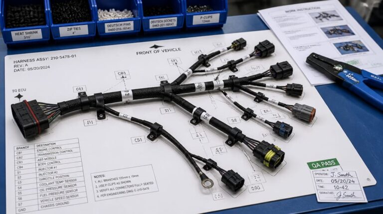
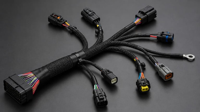
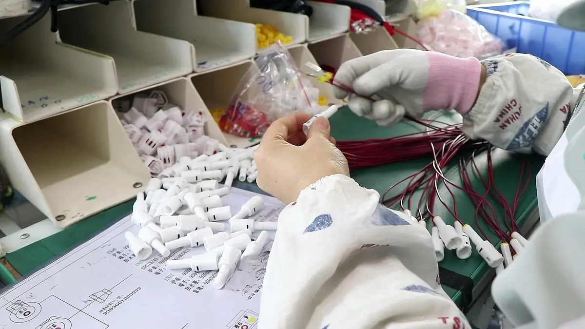
For OEM programs that move from connector verification into completed cable assemblies, the same discipline applies to drawing review, sample confirmation, continuity testing, and appearance inspection. A custom cable assembly supplier can use the verified connector list to specify cut length, strip length, wire type, and routing before crimping begins. In larger builds, the connector verification should be written into the wire harness manufacturing instruction set so that terminal and tooling part numbers are locked at the same time as the routing board.
Export packaging and incoming warehouse receiving are part of the same package. Labeled bags or trays, moisture protection where required, and matched receiving documents reduce the risk of incorrect connectors being pulled at the warehouse dock. Quality inspection and export packaging should follow the same go/no-go logic as the connector cross-check.
To prevent connector BOM mismatch from halting your build, EDOM Electronics integrates upfront DFM engineering review with high-speed manufacturing: we verify connector drawings and mating-pin compatibility within 24 hours, provide rapid wire harness prototyping in 3–5 days, and validate crimp integrity through micro-section cross-sectional analysis and 100% electrical continuity testing.
For buyers who need specification review across multiple connector families, electronic connector sourcing and matching support can be part of the same workflow.
Frequently Asked Questions
Is JST XH the same as a 2.54 mm pin header?
No. JST XH is a 2.50 mm pitch wire-to-board connector with crimp contacts. A 2.54 mm header is a different centerline spacing. Even a small difference per pitch accumulates across multiple pins and can prevent reliable mating on high-pin-count boards.
What information is required to quote a JST connector?
The buying document should include series, pitch, circuit count, termination style, wire gauge, and full manufacturer part numbers for both the housing and the mating half. A BOM line that reads only “JST connector” is not sufficient for an accurate quote.
Can one generic crimp tool work for all JST series?
No. Different series and terminal part numbers use different die profiles and crimp heights. Generic crimp tools may produce partial crimps, cracked terminal barrels, or insufficient insulation support. Use tooling matched to the specific terminal.
Does pitch alone identify a JST series?
Pitch narrows the candidates, but it is not enough. Termination style, contact profile, keying, and mating half geometry must also be checked. Some series may share a nominal pitch but differ in terminal profile and current path.
How should buyers prevent “JST connector” BOM stalls?
Use a series cross-check before quoting. Require full part numbers for both connector halves, verify pitch and wire gauge, and add drawing review, sample confirmation, continuity testing, and appearance inspection to the sourcing gate. If any column fails, stop and request the missing specification.
Key Takeaways
- “JST connector” is a manufacturer name and product family, not a part number. The BOM must identify series, pitch, circuit count, termination style, and mating half.
- JST XH at 2.50 mm pitch is not a drop-in replacement for a 2.54 mm header layout, especially at higher pin counts.
- Pitch alone does not identify a series; terminal profile, wire gauge range, keying, and mating face geometry must be cross-checked.
- IPC/WHMA-A-620 provides practical crimp workmanship and pull-force acceptance criteria, but inspection must verify terminal and tooling compatibility together.
- Full manufacturer part numbers for both connector halves and the crimp contact should be locked before quoting, production, or export packing.