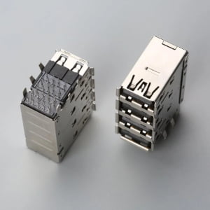
If you’re sourcing a connector(see our What Is a Connector? A Practical Overview for OEM Buyers) from a part number on a drawing and you think matching the pin count and dimensions is enough — this article covers what dimensions don’t tell you and what determines whether the connector will actually work in your assembly.
Direct answer: A DIN connector is a circular connector family originally defined by German standards, with common variants including 5-pin DIN, Mini-DIN, and the MIDI connector. The name identifies an interface standard and mechanical shell, not a single electrical circuit or manufacturer.
Direct Answer: What a DIN Connector Actually Is
The term “DIN connector” comes from Deutsches Institut für Normung, the German standards body. DIN 41524 defines mechanical dimensions and pin assignments for certain circular connectors used in audio and control applications, while IEC 60130-9 is referenced for some related interface dimensions. What matters for sourcing is that DIN describes a family of circular connector shells — not one specific circuit, not one manufacturer, and not one interchangeable part number.
Common variants include the 5-pin DIN used in older audio and MIDI equipment, Mini-DIN connectors with four, six, or eight pins, and the MIDI connector, which physically uses a 5-pin DIN shell but follows a different signal convention. Each variant carries its own keying, pinout, and termination expectations. Two connectors can share the same outer shape and pin count yet still fail in a real assembly because the termination method, plating stack, keyway orientation, or mechanical retention differs.
For procurement and engineering teams, the central risk is treating DIN as a generic drop-in category. Matching shell dimensions answers only one question: will it physically plug in? It does not answer whether the contact will crimp to the specified wire gauge, survive the soldering profile, maintain contact resistance over the required mating cycles, or stay seated in the panel cutout under vibration and handling.
Pin Types, Pinouts, and Keying: Same Shell, Different Circuits
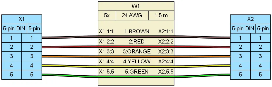
A 5-pin DIN shell can carry audio signals, MIDI data, or control voltages depending on how the cable assembly is wired. The circuit is defined by the pinout, not by the shell. A buyer who assumes that every 5-pin DIN part has the same pin assignment may receive a connector that plugs in but routes signal to the wrong terminal — a failure that often appears only at final test.
The keyway on a DIN connector is the raised or recessed polarizing feature that prevents mis-insertion and sets mating alignment in the panel cutout. Crucially, contact geometry also varies within identical shells: a standard 5-pin DIN is produced in both 180° and 240° pin arc layout configurations (DIN 41524 vs. DIN 45322). An assembly configured with a 240° insert will not mate with a standard 180° socket, even though the shell outside diameter and pin counts are identical.
Mini-DIN makes this distinction more visible. The 4-pin S-video Mini-DIN, the 6-pin PS/2 Mini-DIN, and the 8-pin serial Mini-DIN share a small circular form factor but use different pin counts and keying positions. They are not cross-matable. An S-video plug will not seat correctly in a PS/2 port, despite the visual similarity. For buyers working from an incomplete BOM or a blurry photo, this is a common source of ordering error.
MIDI is often described as a 5-pin DIN connector, but standard MIDI 1.0 current loop data transmission physically terminates three contacts: Pin 4 (Current Source, +5V via resistor), Pin 5 (Current Sink, Data IN/OUT), and Pin 2 (Cable Shield/Ground, tied to chassis ground at the transmitter to prevent ground loops). Pins 1 and 3 remain unconnected in basic assemblies. A MIDI cable requires high-coverage foil/braid shielding and single-end drain grounding rather than the balanced dual-channel audio wiring common in DIN 41524 systems. A cable that passes continuity may still introduce noise or fail under sustained routing if it was built for audio rather than digital control signals.
| Connector Variant | Pin Count & Arc Angle | Standard / Spec | Electrical Rating (Nominal) | Shell OD (mm) | Primary Mating / Pinout Risk |
|---|---|---|---|---|---|
| Standard 5-Pin DIN (180°) | 5 pins @ 180° arc | DIN 41524 / IEC 60130-9 | 34V AC / 3A max | 13.2 mm | Audio vs. MIDI pinout divergence; easily confused with 240° variant |
| Industrial 5-Pin DIN (240°) | 5 pins @ 240° arc | DIN 45322 | 34V AC / 3A max | 13.2 mm | Pin circle spacing prevents mating with 180° DIN sockets |
| MIDI 5-Pin DIN | 5 pins @ 180° arc (3 active) | MIDI 1.0 Current Loop | 5V DC, 5 mA current loop | 13.2 mm | Pin 2 shield must not create chassis ground loop; Pins 1 & 3 NC |
| Mini-DIN 4-Pin | 4 pins + key | EIAJ CP-3401A (S-Video) | 12V DC / 1A max | 9.5 mm | Luminance (Y) and Chrominance (C) ground isolation failure |
| Mini-DIN 6-Pin | 6 pins + center key | IBM PS/2 Specification | 5V DC / 100 mA max | 9.5 mm | Distinct internal keying blocks mating with 4-pin or 8-pin variants |
| Mini-DIN 8-Pin | 8 pins + offset key | Vendor-specific (Apple/Sony) | 30V DC / 1A max | 9.5 mm | Variable internal pin grid patterns between commercial and medical variants |
Termination Compatibility: The Parameter Drawings Often Leave Out
DIN connectors appear in two broad mounting families. PCB-mount types use solder tails that pass through holes or sit on pads. Cable-mount types use crimp contacts or solder-cup terminations for discrete wires. The outer shell drawing rarely communicates tail length, PCB hole pattern, contact type, or the accepted wire gauge range — but those are exactly the parameters that determine whether the part can be assembled on a given production line.
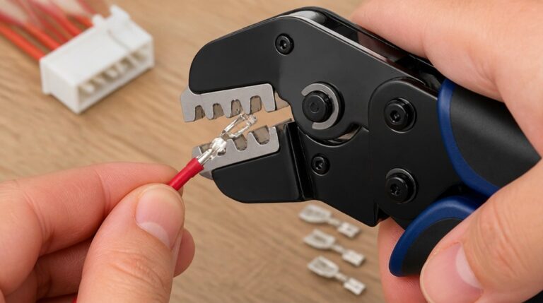
Crimp-style DIN contacts have a narrow wire-gauge acceptance range. If a visually identical connector is selected with a crimp barrel sized for a larger wire, the crimp may not compress fully around the conductor, leading to poor retention, damaged strands, or a high-resistance joint. If the barrel is too small, the assembler may cut strands to make it fit, creating a field failure point that is invisible at incoming inspection.
PCB-type DIN connectors carry soldering process windows and footprint tolerances. A part that looks like the drawing may require different hole diameters, tail lengths, or reflow and wave soldering parameters than the one the board was designed for. Through-hole anchors and board locks must align with the PCB footprint, or the connector will tilt, stress solder joints, or fail to seat before wave soldering.
“We regularly see connectors that pass visual incoming inspection but fail during assembly — the termination interface or plating stack was engineered for a different process than the one running on the production line. The part looks right; the process doesn’t know it’s wrong.”
Before ordering, confirm the termination method against the actual assembly process. Ask for the wire gauge range, contact type, tail length, and PCB footprint drawing. These details are part of a credible drawing review and should be verified before committing to production quantities.
Plating and Retention: What Determines Reliability After It Plugs In
Plating material and thickness govern contact resistance, corrosion resistance, solderability, and mating-cycle life. A thin gold flash over nickel is not functionally equivalent to a heavier gold plating in harsh or high-cycle environments. For industrial controls, test equipment, or outdoor panels, the plating stack must match the environment and the expected number of insertions. A connector that measures fine at first contact can develop intermittent failures after repeated mating if the plating wears through.
Mechanical retention varies across DIN connector designs. PCB-mount versions may rely on through-hole anchors, board locks, or snap-in lugs to hold the connector before and during soldering. Cable-mount versions may use screw collars, latch rings, or friction fit. A visually similar connector with a different retention method may loosen under vibration, pull out during cable routing, or fail to seat firmly in the panel.
The keyway and shell polarizing features interact with panel thickness and cutout dimensions. An incompatible panel fit can place lateral stress on the connector body, transferring load to solder joints and causing intermittent contact. A part that mates correctly in free air can still fail after installation if the shell does not seat flush against the panel or if the latch does not engage at the correct depth. Two connectors can share the same outer diameter and pin count but differ significantly in plating durability and mechanical retention — differences that only become visible after installation or repeated mating.
Compatible vs Interchangeable: A Sourcing Distinction
In connector sourcing, “compatible” and “interchangeable” are not the same. A compatible connector is functionally fit for a defined application: it can handle the required signals, wire gauge, and environment. An interchangeable connector is a true drop-in match for the mating connector, panel cutout, termination process, and electrical requirements without process changes. Buyers who treat compatible as interchangeable create line-down risk when the first production batch arrives.
The MIDI example illustrates the gap. A MIDI DIN cable assembly may be electrically compatible for MIDI signals — it carries the two active data pins and provides shielding — but it may not be interchangeable with an audio 5-pin DIN assembly if the pin usage, shell construction, or mating retention differs. The equipment may work in a bench test, then fail in the field because the connector does not seat firmly in the equipment chassis or the shield continuity is not maintained.
Branded series part numbers carry controlled drawings and tolerances for keyway dimensions, pin diameter, and plating thickness. Generic or no-name alternatives may drift in any of these parameters, even when the outer shape looks correct. Before accepting an alternative, compare the mating connector, the panel cutout, the termination process, and the environmental exposure. The lowest-risk path is to test samples against the existing mating connector or a confirmed golden sample before releasing production quantities.
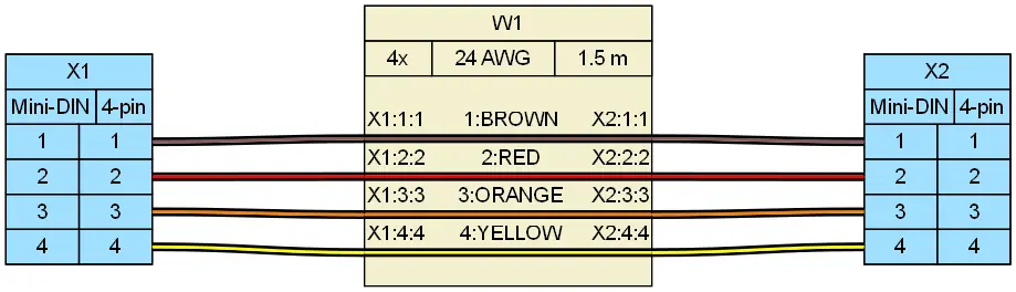
Connector Verification Checklist Before You Order
Use this five-point check before placing an order for any DIN connector or cable assembly that uses one. It turns the hidden compatibility risks into a repeatable gate.
- Termination method: Confirm solder, crimp, IDC, PCB through-hole, or panel mount matches the production process.
- Plating specification: Confirm the contact plating stack and underplate meet environmental exposure and mating-cycle requirements.
- Key dimensions: Verify outside diameter, panel cutout, pin diameter, keyway position, tail length, and PCB hole pattern with actual samples.
- Mating interface: Confirm pin count, pin location, keying, shell size, thread or latch mechanism, and insert orientation are fully identical.
- Documentation: Obtain the pinout drawing, wire gauge range, and RoHS status for the exact part number before committing.
If you have a drawing, BOM line, connector photos, and target assembly process, submit them for a compatibility review that covers termination, plating, retention, and sample confirmation. A supplier that checks these parameters before quotation can save the rework that appears when a connector passes visual inspection but fails on the line.
From Verification to Production: Sourcing DIN Connectors for Real Assemblies
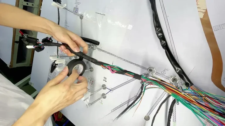
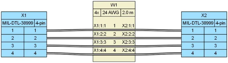
Once the verification checklist passes, the next step is sample confirmation. Request dimensional drawings, termination samples, and mating samples from the supplier. Test the fit against the existing receptacle or panel cutout, and confirm the soldering or crimping process window before releasing bulk supply. For custom cable assemblies that integrate DIN connectors, the drawing review should cover connector matching, crimping, continuity testing, and labeling. For wire harness manufacturing projects, connector verification must be complete before routing, looming, and final inspection begin.
OEM and wholesale buyers can reduce line-down risk through structured incoming inspection. Continuity and appearance checks on finished cable assemblies catch open pins, damaged keyways, and plating defects before the parts reach production. EIA-364 defines a series of test procedures for electrical connectors and sockets that many OEM qualification programs use to verify mechanical and environmental performance. Export packaging also matters: the packaging should protect DIN pins, keyways, threads, and terminal tails during international shipping, warehouse receiving, and OEM production use.
For custom DIN and Mini-DIN cable integration, engineering teams avoid qualification delays by validating manufacturing tolerances upfront. EDOM Electronics delivers full-cycle OEM/ODM cable assembly and wire harness manufacturing—from 3–5 day rapid prototype tooling and DFM crimp barrel validation to 100% low-resistance continuity and dielectric breakdown testing (EIA-364). Contact our engineering team with your 2D CAD drawings, pinout schematics, or target mating shell samples to lock down tooling and pre-production inspection before full-run releases.
Frequently Asked Questions
Is a DIN connector the same as a MIDI connector?
Not exactly. MIDI equipment commonly uses a 5-pin DIN connector shell, but the MIDI interface uses a specific pin assignment and often active pins on only two positions. A MIDI cable assembly may differ in shielding and pin usage from an audio 5-pin DIN cable, so the two are not automatically interchangeable.
Can I use a 4-pin Mini-DIN cable in a 6-pin Mini-DIN port?
No. Mini-DIN variants have different pin counts and keying positions. A 4-pin S-video plug will not seat correctly in a 6-pin PS/2 port. The outer shape is similar, but the keyway and pin layout prevent cross-mating without forced insertion and damage.
What should I check on a drawing before ordering DIN connectors?
Confirm the termination method, contact type, wire gauge range for crimp contacts, tail length and PCB hole pattern for PCB-mount types, plating stack, keyway position, panel cutout dimensions, and the complete pinout. Dimensions alone are not enough to verify a part for production.
Are DIN connectors RoHS compliant?
RoHS-compliant options are widely available for DIN connectors, but compliance is part-specific. Buyers should confirm RoHS status in the BOM documentation for the exact part number, including any cable assembly or connector kit involved, because the restricted substance limits apply to the finished component.
Do I need to test a sample before full production?
Yes. A sample test against the existing mating connector or a confirmed golden sample is the most reliable way to verify keyway fit, pin alignment, termination compatibility, and plating appearance before committing to bulk quantities. This step catches issues that datasheet drawings and photographs do not reveal.
Key Takeaways
- DIN is a circular connector family, not a single circuit or manufacturer. PIN count and outer shape establish shell compatibility only.
- Termination method is the first hidden parameter: crimp wire gauge range and PCB soldering footprint must match the actual assembly process.
- Plating stack and mechanical retention determine long-term reliability after installation, even when the connector plugs in correctly at first.
- “Compatible” is not the same as “interchangeable.” A true drop-in replacement must match the mating connector, panel cutout, termination process, and environmental requirements.
- Sample verification against a golden sample or existing mating connector is the most effective pre-order gate for DIN connector sourcing.
For broader connector families and sourcing support, explore electronic connector sourcing options.