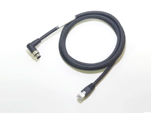
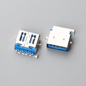
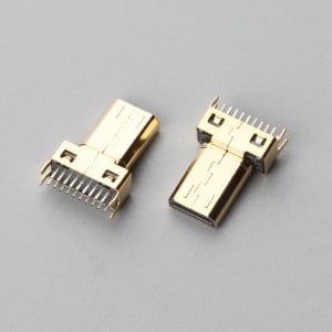
Direct answer: A marine wire harness manufacturer is a specialized cable and wiring assembly supplier that builds loomed, terminated, and sealed harnesses for vessel electrical systems, using tinned copper conductors, moisture-resistant insulation, and sealed connector interfaces validated against ABYC E-11 pathways and IPC/WHMA-A-620[1] workmanship acceptance criteria for wet, vibration-prone operating environments, as discussed in How Specialized Cable Assemblies Solve OEM Design Challenges.
Does either situation sound familiar? A procurement manager receives a supplier BOM for a new navigation system listing automotive-grade connectors and bare copper wire alongside marine-electronics components. Or a project lead inherits a previous marine harness build that passed continuity but returned from the field with green corrosion at the pins and intermittent opens after one season.
The hidden failure is that receiving inspection checks pinout and continuity, but salt-fog wicking, untinned copper, and unsealed crimps are invisible until the harness reaches salt spray, vibration, and heat. The decision now is whether supplier sign-off will be evidence-based and standard-driven, not sample-approval-based.
How to Verify a Marine Wire Harness Manufacturer Before Sign-Off
Step 1: Lock the Electrical and Materials Baseline Before Quoting
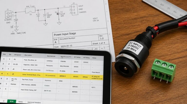
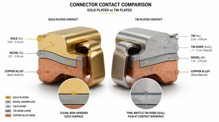
Treat the BOM review as a decision gate, not a quotation formality. Before any quote is accepted, confirm pinout, wire gauge, insulation temperature rating, conductor tinning, and connector contact plating, a factor also covered for agricultural machinery in Agriculture Wiring Assemblies: What OEM Buyers Need to Know. Marine applications expose conductors to moisture, salt, and temperature cycling, so bare copper should be rejected for wet or damp locations. Require tinned copper conductors per ABYC E-11 and check whether insulation options such as UL 1426[2] are needed for the vessel circuits.
Do not assume automotive wire is automatically marine-grade. SAE J1128[3] may be acceptable only if its insulation temperature rating and moisture performance align with the vessel environment. For low-voltage DC systems, use ISO 10133[4] or ABYC E-11 as the baseline depending on vessel type and flag. The standard becomes the decision threshold, not the supplier’s verbal assurance.
- Confirm pinout, AWG, insulation temperature rating, and contact plating in the quote.
- Require tinned copper conductors for wet or damp locations.
- Check UL 1426 insulation where the vessel system calls for marine-rated cable.
- Do not accept SAE J1128 automotive wire unless its temperature and moisture performance align with the marine environment.
- Use ABYC E-11 or ISO 10133 as the low-voltage DC decision threshold depending on vessel type and flag.
Step 2: Distinguish an Acceptable Second-Source Terminal from a Reject Substitution
An acceptable second-source terminal is not an “equivalent” on paper. It must match the connector system, contact plating, wire range, and tooling requirements for form, fit, and function. Require pull-force records and crimp-height measurements tied to IPC/WHMA-A-620 Class 3 workmanship. Vague equivalent-terminal claims without test data should trigger a hold-sign-off response.
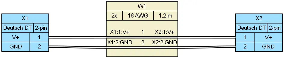
Watch for non-ratcheted or uncalibrated tooling substitutions. These often pass continuity but cause under-crimping, over-crimping, or vibration-induced fretting later, as discussed in Rugged Robotics Cable Assemblies: Key Design Considerations. If a Deutsch DT or other sealed connector is specified, verify that the terminal, wedge lock, and seal match the exact housing part number. Mixed terminal families are a hold-sign-off condition. This is especially important for custom cable assemblies that combine multiple connector families in one service loop.
Step 3: Run the Go/No-Go Supplier Verification Table Before Sign-Off
Use the following table as a go/no-go control before PO release or engineering sign-off. Each row converts an invisible marine risk into a documented verification point.
Marine Harness Supplier Verification: Go/No-Go Before Sign-Off
| Verification Point | Verify Evidence | Hold Sign-Off |
|---|---|---|
| Tinned copper conductors per ABYC E-11 | Material certification or supplier declaration identifying tinned copper, not bare copper | Bare copper or unverified plating appears in quote or BOM |
| Sealed connector face and mating interface | IP67-rated connector face with production samples or drawings for Deutsch DT or NMEA 2000 style interfaces | Open-face or unsealed connectors appear on exposed runs |
| Pull-force and crimp-height evidence | Crimp process data or sample pull-force reports aligned to IPC/WHMA-A-620 Class 3 | No tooling or process records, or visible wire-strand damage |
| Harness bend radius for dynamic runs | Routing drawing or layout check confirming bend radius margins for cables and harness branches | No routing dimension, or bend radius equals minimum at rest |
| Sub-harness lead time acknowledged | Written schedule or capacity confirmation from supplier for all sub-harness and fabrication work | Main assembly date assumes sub-harnesses arrive without supplier confirmation |
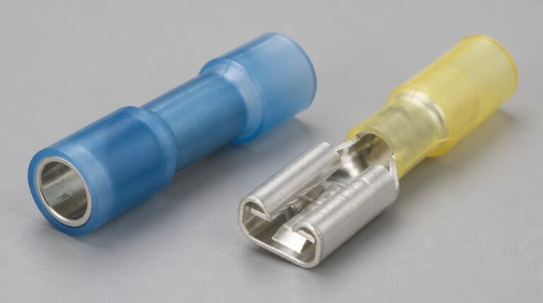
| Longitudinal Water Intrusion / Wicking Protection | Sealed splice joints using adhesive-lined heat shrink (dual-wall polyolefin) or potted transitions | Standard single-wall heat shrink or unsealed inline splices present. |
The table catches salt-fog wicking, untinned copper, and unsealed crimps before they become field failures. A supplier that cannot produce evidence for a row should not receive sign-off on that point.
Step 4: What Goes Wrong in the Field
Review each field failure as a missing supplier-verification point, not an isolated warranty claim. The following marine-specific conditions show why continuity-only inspection is not enough.
- Salt-fog wicking into unsealed crimps: green corrosion or intermittent opens at the pin after one season. Catch before shipment by requiring sealed connectors and crimp or plating evidence.
- Vibration-induced fretting from non-ratcheted tooling: micro-arcing, blackened contact spots, or intermittent signal dropout. Catch with pull-force and crimp-height data from validated ratcheted tooling.
- Jacket-color substitution without an ECO: wrong harness identification, misrouting, or warranty disputes. Catch by locking color, marking, and ECO approval into the drawing before production.
- Recycled resin connector housings cracking in sunlight or heat: cracked, chalky, or deformed housings near engine heat or deck sun exposure. Catch by specifying UV-stabilized or marine-grade housing resin and rejecting unidentified regrind.
Step 5: Enforce Zero Tolerance on CCA and Require an Engineering Change Order for Resin or Marking
Cosmetic-looking changes can be safety-relevant in marine harnesses. Jacket color and marking changes affect routing, circuit identification, and service documentation, so require a formal engineering change order before accepting any substitution. A changed resin in connector housings affects sunlight, heat, and impact performance; accept it only with UV-stabilized material data and updated part documentation.
CCA-to-copper substitution is an immediate, non-negotiable reject under ABYC E-11 and ISO 10133—aluminum and copper-clad aluminum conductors are strictly prohibited in vessel branch circuits due to galvanic corrosion and flex fatigue. Do not evaluate CCA via an ECO; reject it outright. If a proposed change violates ABYC E-11, IEC 60092-350[5], or IPC/WHMA-A-620 workmanship intent, reject it.
- Require formal ECO for jacket color, marking, or resin changes.
- Accept changed resin only with UV-stabilized material data and updated part documentation.
- Enforce zero tolerance on CCA: reject copper-clad aluminum outright, as ABYC E-11 and ISO 10133 strictly prohibit non-copper/untinned conductors in vessel branch circuits.
Step 6: Schedule Operator Skill and Sub-Harness Lead Times with the Main Assembly
Sub-harness lead time and operator soldering skill are schedule inputs, not afterthoughts. Require evidence of IPC/WHMA-A-620 Class 3 soldering and crimping competency for operators, not just a QMS certificate. Confirm sub-harness lead times are acknowledged against the main assembly date; hidden feeder parts are a common late-delivery cause.
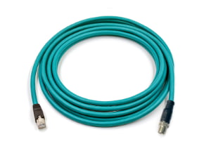
Ask whether cutting, stripping, crimping, routing, labeling, and looming are scheduled as a coordinated sequence. If sub-harness routing is quoted without a level of effort, hold sign-off. For NMEA 2000 drop and backbone interfaces, require connector-specific build instructions and test access in the production plan.
For OEM programs with multiple sub-harnesses and connector families, a supplier that coordinates requirement review and production follow-up can reduce the burden of chasing evidence across process owners. To eliminate cross-process tracking risks, OEM procurement should require suppliers to integrate these verification records into an Engineering Sign-Off Packet. For example, in EDOM’s standard NPI marine workflow, conductor mill test certificates, automated crimp pull-test logs, and dual-wall seal inspection data are tied directly to the assembly traveler sheet prior to export packaging release. These evidence items should be included in the quality inspection and export packaging record so receiving inspection is not limited to continuity-only checks.
Step 7: Release Sign-Off Only When No Hold Items Remain
Release sign-off only when the go/no-go table shows no Hold sign-off items open. A marine wire harness manufacturer should be judged by documented evidence—tinned copper, sealed connector faces, crimp data, routing review, and lead-time acknowledgment—not by generic certificates on the wall.
The next action is specific: send the table to the supplier with the BOM, sample, or drawing and require evidence against each verification point before the quotation is accepted. ABYC E-11, IEC 60092-350, and IPC/WHMA-A-620 Class 3 then become working decision thresholds, not references in a quality manual.
Frequently Asked Questions
What is the difference between ABYC E-11 and ISO 10133 for marine low-voltage harnesses?
ABYC E-11 is commonly applied to low-voltage DC systems on recreational vessels, while ISO 10133 is used for certain vessel types and flags. Both define conductor insulation, tinning, routing, and protection requirements. The applicable standard should be locked into the drawing and quote before sign-off.
Can SAE J1128 automotive wire be used in a marine harness?
Not automatically. SAE J1128 may be considered only if its insulation temperature rating and moisture performance align with the vessel environment. For wet or damp locations, tinned copper conductors and marine-rated insulation such as UL 1426 should be specified.
Can a supplier substitute an equivalent terminal if the original sealed connector is unavailable?
Only if the terminal matches the connector system, housing part number, plating, wire range, and validated crimp tooling. For Deutsch DT or other sealed systems, the terminal, wedge lock, and seal must match exactly. Mixed terminal families are a hold-sign-off condition.
What should a marine harness verification package include before sign-off?
It should include material certification for tinned copper, sealed connector face documentation such as IP67-rated interfaces, pull-force and crimp-height records aligned to IPC/WHMA-A-620 Class 3, routing drawings with bend radius margins, and written sub-harness lead-time acknowledgment.
What documentation should an OEM require before approving a marine wire harness production sample?
An OEM should require a complete Engineering Sign-Off Packet before sample approval, including raw material certificates for tinned copper per ABYC E-11, crimp-height and pull-force data conforming to IPC/WHMA-A-620 Class 3, IP67/IP68 ingress verification, and a confirmed sub-harness production schedule. Manufacturers such as EDOM Electronics package these quality inspection and traveler records directly with NPI prototype shipments to ensure receiving inspection is not limited to basic continuity checks.
Key Takeaways
- Lock pinout, AWG, insulation temperature rating, tinned copper, and connector contact plating into the BOM and quote before commercial sign-off.
- Use the go/no-go table to verify tinned copper per ABYC E-11, sealed connector face, pull-force and crimp-height evidence, bend radius, and sub-harness lead time.
- Reject bare copper and CCA-to-copper changes outright with zero tolerance; require a formal ECO and material validation before accepting any resin, marking, or terminal substitutions.
- Require IPC/WHMA-A-620 Class 3 evidence for crimp and soldering workmanship and schedule operator competency with the main assembly.
- Release sign-off only after all Hold sign-off items are resolved and the evidence is recorded in the quality inspection and export packaging file.
For OEM buyers preparing a marine harness RFQ, the go/no-go table is the practical starting point. Explore custom wire harness manufacturing support for marine and other operating environments.