Before you finalize a connector selection, answer these core engineering questions: Has the PCB layout been routed on a metric 2.50mm grid or a standard 0.1-inch (2.54mm) imperial grid? What is the pin count, current rating, and wire gauge (AWG)? Will the harness operate in a benign enclosure or be exposed to moisture, wide temperature swings, and vibration? If you are evaluating a cross-reference or sorting BOM specifications, verify these physical and electrical boundaries before ordering.
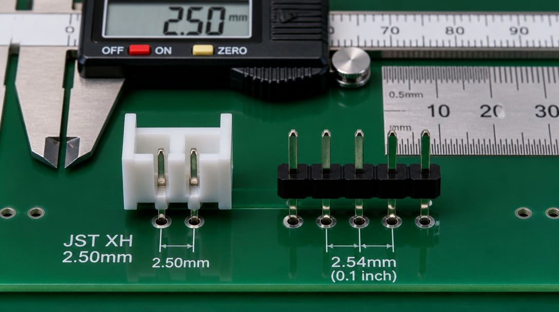
Direct answer: JST XH is a 2.50mm pitch wire-to-board connector family that uses crimp contacts and PCB headers for board-level signal and low-power connections; 2.54mm pitch is the 0.1 inch grid used by Molex KK 254 and generic 0.1 inch headers, differing by 0.04mm per position and creating different PCB header pad spacing and mating compatibility.
How to Compare JST Connector Pitch 2.50mm vs 2.54mm for Wire-to-Board Applications
Step 1: Confirm the Pitch Difference Is Physical, Not a Labeling Variance
The first action is to confirm whether the PCB layout has been designed for 2.50mm or 2.54mm pad spacing. JST XH is a 2.50mm pitch wire-to-board connector system. A generic 0.1 inch header and the Molex KK 254 series use a 2.54mm pitch. The 0.04mm difference per position compounds across the connector width and shifts each pad location enough to create interference, open contacts, or housing misalignment when the wrong crimp contact and PCB header are combined.
Do not treat JST XH and a 2.54mm header as drop-in substitutions. A JST XH crimp contact is dimensioned for the 2.50mm housing cavity and retaining lance. The PCB header mating face and keying geometry are not the same even when the parts look similar in photographs. For a broader view of how mechanical, electrical, and environmental roles interact in any connector family, see the practical connector overview for OEM buyers.
Cumulative Pitch Deviation Formula:
Cumulative Offset = (Pin Count – 1) × 0.04 mm
Because the pitch difference is 0.04 mm per circuit, the total mechanical displacement compounds across the header width as shown below:
| Pin Count (N) | Nominal 2.50mm Span (JST XH) | Nominal 2.54mm Span (0.1″ Grid) | Cumulative Pitch Offset | Mating & Reliability Impact |
|---|---|---|---|---|
| 2-Pin | 2.50 mm | 2.54 mm | 0.04 mm | May mate with slight force; causes terminal beam preload fatigue. |
| 3-Pin | 5.00 mm | 5.08 mm | 0.08 mm | Noticeable insertion resistance; terminal pin scraping and plating wear. |
| 4-Pin | 7.50 mm | 7.62 mm | 0.12 mm | Plastic shroud interference; bent header pins and intermittent contact. |
| 5-Pin to 10-Pin+ | 10.00 mm – 22.50 mm | 10.16 mm – 22.86 mm | 0.16 mm – 0.36 mm | Complete mating failure. Pins jam, buckle, or crack the housing. |
Step 2: Resolve Three Environment Questions Before Electrical Ratings
Once the pitch is confirmed, move to the conditions the connector will see after installation. IEC 60529[1] defines IP ratings for solids and liquids. EIA-364[2] covers electrical, mechanical, and environmental test procedures for connectors and sockets. These two references should guide the conversation before current rating, voltage, or mating cycles. If the site may see water spray, condensation, washdown, or fine dust, define the required IP level first.
In our experience, the single most useful thing a buyer can tell us is where the connector will actually be installed. Mounted next to a diesel engine outdoors tells us more than ten pages of electrical drawings when it comes to connector selection.
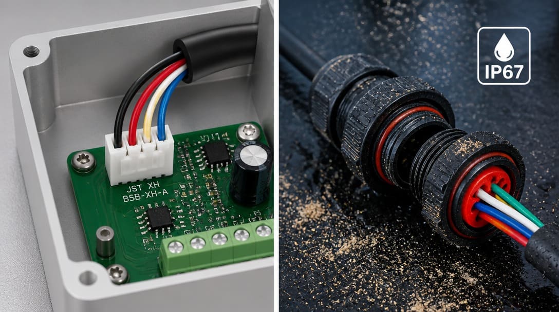
An open JST XH or Molex KK 254 header may be acceptable in a clean indoor enclosure, but the same pitch choice beside an outdoor diesel pump or under a vehicle splash zone introduces different requirements for sealing, terminal plating, and retention. Ask the three environment questions before comparing part numbers.
Step 3: Sort Requirements into Indoor/Benign and Outdoor/Harsh Outcomes
Use the following table to separate benign applications from harsh ones. This prevents a visually similar connector from driving a decision that should be controlled by installation conditions.
| Selection Criterion | Indoor / Benign Environment | Outdoor / Harsh Environment |
|---|---|---|
| Connector pitch / type | JST XH 2.50mm or 2.54mm header may be acceptable | Open JST XH or KK 254 may need sealing, strain relief, or an alternative series |
| Mating risk | Check PCB header footprint and housing keying | Add locking, positive latch, and retention review |
| Moisture / dust requirement | IP rating may be unnecessary in a clean enclosure | Define IEC 60529 IP level for spray, condensation, or washdown |
| Temperature requirement | Standard operating range may be sufficient | Verify EIA-364 temperature cycling and material behavior |
| Vibration / shock requirement | Low risk if the board is fixed and protected | Requires crimp contact retention and PCB header strain relief |
| Likely decision outcome | Proceed to electrical verification | Re-evaluate sealing, terminal plating, and retention before ordering |
For a connector matching review based on your actual installation environment, move from a visual shortlist to a production-ready choice by reviewing the PCB header drawing and crimp contact specification together.
Step 4: Verify Current, Voltage, Wire Gauge, and Crimp Contact Fit
After confirming physical pad spacing, cross-reference the electrical and mechanical ratings. JST XH and 2.54mm wire-to-board systems differ in current limits, contact resistance, and wire insulation tolerances:
| Specification Parameter | JST XH Series (2.50mm) | Molex KK 254 Series (2.54mm) | Standard 0.1″ Dupont Header |
|---|---|---|---|
| Pitch (Center-to-Center) | 2.50 mm (0.098 in) | 2.54 mm (0.100 in) | 2.54 mm (0.100 in) |
| Current Rating | 3.0A AC/DC (AWG #22) | 4.0A – 4.75A AC/DC | 1.0A – 2.0A (Typical) |
| Voltage Rating | 250V AC/DC | 250V / 500V AC/DC | 250V AC/DC |
| Applicable Wire Range | AWG #30 to #22 (OD 0.9–1.9 mm) | AWG #30 to #22 (OD up to 1.57 mm) | AWG #28 to #24 |
| Locking & Keying Mechanism | Friction lock, keyed shroud | Friction ramp & polarizing rib | Friction only, non-polarized |
| Typical Contact Resistance | ≤ 10 mΩ initial | ≤ 20 mΩ initial | ≤ 30 mΩ initial |
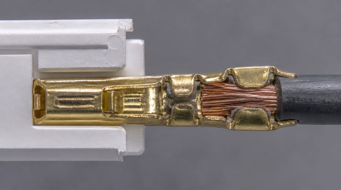
A crimp contact sized for the wrong wire gauge can fail continuity under temperature cycling even if the connector family is correct. When the connector is integrated into a cable assembly, the drawing package should define cable structure, strip length, crimp tooling, and testing. Buyers can reduce project risk by reviewing these details before ordering samples; for related production coordination, see custom cable assembly support.
Alternative 2.54 mm Pitch Wire-to-Board Connector Families
If your PCB layout is fixed on an imperial 0.1-inch (2.54 mm) grid, do not force 2.50 mm connectors onto the board. Select a dedicated 2.54 mm pitch wire to board connector family designed to handle the appropriate retention, current carrying capacity, and latching requirements:
| Connector Family | Pitch | Current Rating | Locking Type | Typical B2B Applications |
|---|---|---|---|---|
| Molex KK 254 (Series 6471 / 2695) | 2.54 mm (0.100″) | 4.0 A – 4.75 A | Friction ramp & polarizing rib | Power supply boards, automotive modules, industrial controls |
| JST RE / RF / RA Series | 2.54 mm (0.100″) | 2.0 A – 3.0 A | Friction lock / Polarized housing | Internal board-to-board and wire-to-board instrumentation |
| TE Connectivity MTA-100 / EI Series | 2.54 mm (0.100″) | 3.0 A – 5.0 A | IDC mass termination / Crimp lock | Commercial equipment, white goods, wire harnesses |
| Amphenol FCI Mini-Latch | 2.54 mm (0.100″) | 3.0 A | Positive active latch | High-vibration medical and industrial electronics |
When switching your BOM to a genuine 2.54 mm pitch wire-to-board connector, confirm mating pin height, header wall thickness, and terminal crimp pull-off force with your harness assembly drawing.
Step 5: Confirm Vibration, Temperature, and Sealing with EIA-364 and IEC 60529
EIA-364 test methods cover vibration, mechanical shock, and temperature cycling for connector systems. For a 2.50mm or 2.54mm wire-to-board connector in harsh service, request evidence that the crimp contact and PCB header maintain electrical continuity under the expected mechanical loads. IEC 60529 IP ratings specify ingress protection when dust, water spray, or temporary immersion is possible.
No generic pitch choice solves environmental risk by itself. The housing, sealing method, terminal plating, and PCB header retention must be evaluated together. A sealed connector may require different mounting hardware, potting, or conformal coating. In production, continuity testing and appearance inspection should be defined before export packaging is prepared; see quality inspection and export packaging considerations for a practical view.
Step 6: Turn the Confirmed Shortlist into a Stable Production Order
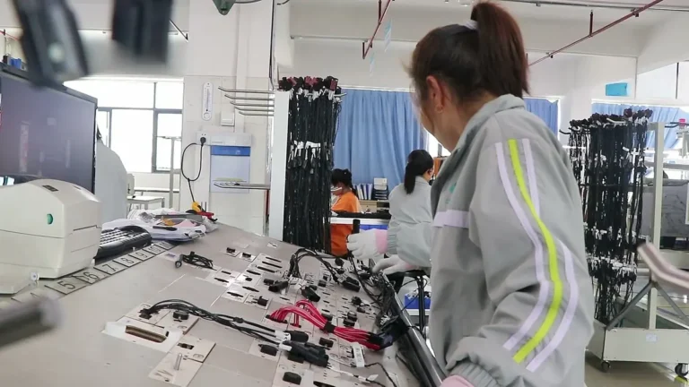
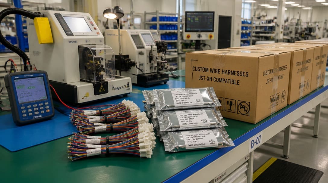
Before ordering, request or review the following items: actual PCB header drawing and footprint, crimp contact wire gauge range, housing keying and locking, IP rating if required by IEC 60529, and EIA-364 test evidence if the application is not benign. If the connector feeds into a wire harness, verify cutting, stripping, crimping, routing, labeling, and continuity checks in the production control plan. Suppliers such as EDOM Electronics support OEM buyers with requirement review, connector matching, sample coordination, production follow-up, inspection, and export-ready packaging for custom cable assemblies and wire harnesses; this kind of structured review helps keep the selected pitch from becoming a late-stage sourcing risk. For wire harness and loom production details, see wire harness manufacturing support.
Frequently Asked Questions
Can a JST XH 2.50mm connector plug into a 2.54mm 0.1 inch header?
No. The 0.04mm per-position difference changes PCB header pad spacing and housing geometry. Crimp contacts and housings are not interchangeable across those pitches.
Is Molex KK 254 the same as JST XH with a different brand name?
No. Molex KK 254 uses a 2.54mm pitch, while JST XH uses 2.50mm. They are separate wire-to-board connector families with different PCB header footprints and mating dimensions.
Do all JST XH applications need an IP-rated sealed connector?
No. An open JST XH header can be appropriate in a clean indoor enclosure. Use IEC 60529 to decide the IP level when moisture, dust, splash, or washdown is present.
What should I request before ordering JST XH or 2.54mm header samples?
Request the actual PCB header drawing, crimp contact wire gauge range, housing keying and locking details, and any EIA-364 test evidence if the equipment will see vibration or temperature extremes.
Can a sourcing partner help confirm a connector alternative?
Yes. A partner can review the installation environment, PCB footprint, and crimp contact specification, then coordinate samples and inspection before production.
Does JST manufacture genuine 2.54mm (0.1 inch) pitch connectors?
Yes. While the popular XH series is strictly 2.50mm, JST manufactures true 2.54mm (0.1 inch) pitch systems under other series names, such as the JST RE, RF, and RA connector series. If your PCB design requires a 2.54mm grid with JST-grade reliability, specify these series instead of XH.
What should I do if a PCB was accidentally routed for 2.54mm instead of 2.50mm JST XH?
If PCB prototypes have already been fabricated with 2.54mm pin spacing, do not force 2.50mm JST XH headers into the board. Instead, switch the BOM to an authentic 2.54mm wire-to-board system (such as Molex KK 254 series or TE Connectivity EI series) and build a matching custom wire harness to avoid reliability and pin-stress failures.
Key Takeaways
- Treat 2.50mm and 2.54mm pitch as physically different, not a rounding error; verify the PCB header footprint before substituting.
- Ask the three environment questions first: moisture, temperature, and vibration/shock.
- Use IEC 60529 for IP ratings and EIA-364 for vibration, shock, and temperature test references.
- Compare electrical specs and crimp contact wire gauge only after environment and PCB layout are confirmed.
- Review drawings, samples, and production inspections before ordering to prevent a late-stage sourcing mismatch.
For electronic connector sourcing and custom cable assembly options matched to the confirmed environment and pitch requirements, explore electronic connector support for OEM and wholesale buyers.