If your cable assembly inspection ends when the continuity tester shows green, you’re catching open circuits and short circuits — but not the two failure modes that cause most field returns.
Direct answer: A crimp quality defect is a mechanical or dielectric failure in the terminal-to-conductor joint that continuity testing cannot detect, characterized by insufficient conductor barrel compression, low pull force retention, or insulation damage, and is verified through crimp height measurement, pull force testing, and hi-pot testing per IPC/WHMA-A-620.
Why Continuity Testing Is Necessary but Not Sufficient
Continuity testing confirms that an electrical path exists and catches open circuits, short circuits, and miswires. It does not measure crimp height, conductor barrel compression, or the condition of the insulation support crimp. A loose crimp with only a few strands of a stranded copper conductor in contact can still light a continuity tester but fail under vibration, thermal cycling, or mechanical load. Contact resistance may also be high even when continuity passes, creating localized heat and intermittent faults that only appear after installation.
For readers needing the broader component definitions behind harness assembly, the pillar overview at What Is a Wiring Harness? Key Components, Functions & Applications supplies the foundation. The key point here is that a green light proves a circuit exists, not that the crimp is mechanically sound or dielectrically safe.
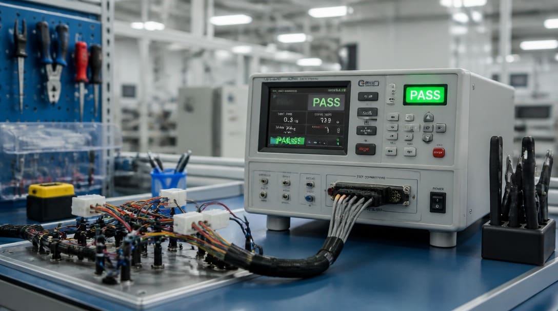
Crimp Quality Defects Hiding Behind a Green Light
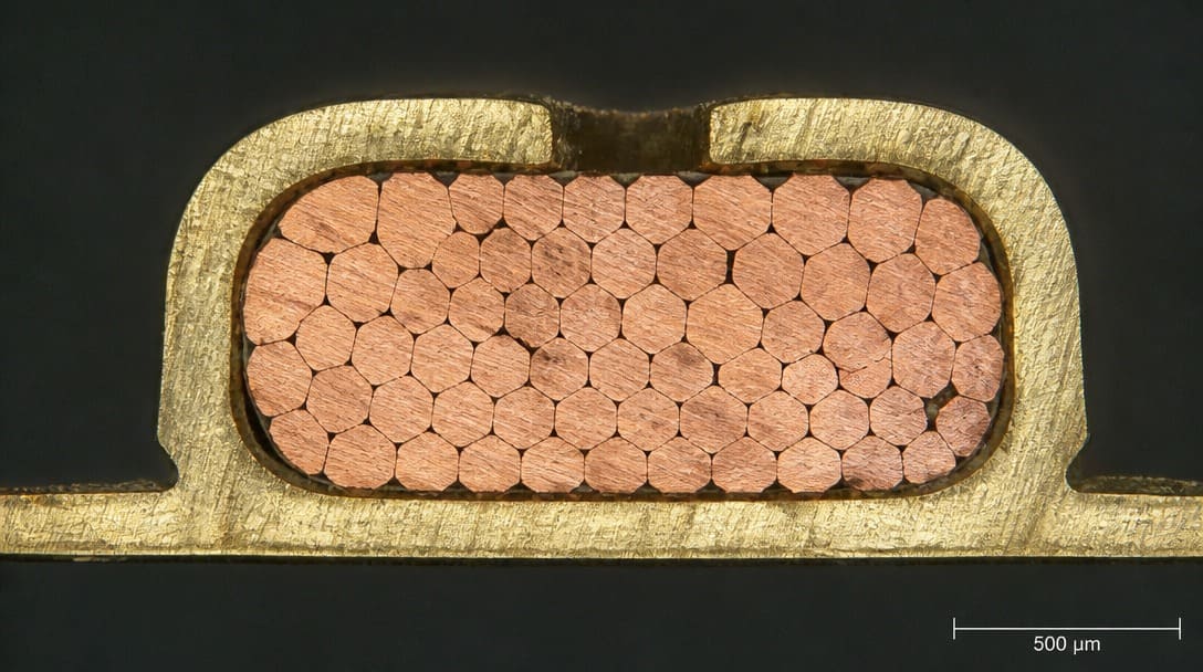
Under-crimped or over-crimped conductor barrels alter crimp height and can break individual wire strands or reduce retention force. A missing or mispositioned insulation support crimp leaves the wire insulation unsupported and allows the stranded copper conductor to flex at the terminal entry point. Over time, that flexing creates fatigue at the transition zone even though the assembly passes continuity during final test.
Microsection analysis is the only reliable way to see internal conductor barrel fill, strand damage, and voiding that external inspection misses. Pull force testing quantifies retention of the crimped stranded copper conductor, while contact resistance testing checks the electrical joint under load. For custom cable assembly projects, defining these inspection methods before tooling release prevents recurring field problems. Custom cable assembly buyers should specify acceptance criteria for crimp geometry, pull force, and contact resistance in the initial drawing review, not after production has started.
Test Coverage Table: Continuity vs. Pull Force vs. Hi-Pot
Three common tests answer different questions. Mapping where incoming inspection currently stops against this table makes the blind spots visible.
| Test Method | Catches | Misses | Typical Application Point |
|---|---|---|---|
| Continuity test | Open circuits, short circuits, miswires | Crimp retention force, contact resistance, insulation breakdown | Every completed assembly for routing verification |
| Pull force test | Low crimp retention force, partial strand capture | Inter-wire shorts, insulation nicks, dielectric faults | Process qualification, per-lot sampling, after tooling change |
| Hi-pot test | Insulation breakdown, nicked insulation, creepage failures | Open circuits, local crimp geometry, mechanical retention | Safety-critical circuits, multi-conductor cables, harsh-environment applications |
Once a defect is caught, final verification includes appearance inspection, export packaging, and shipment preparation. For those controls, see the guide on quality inspection and export packaging.
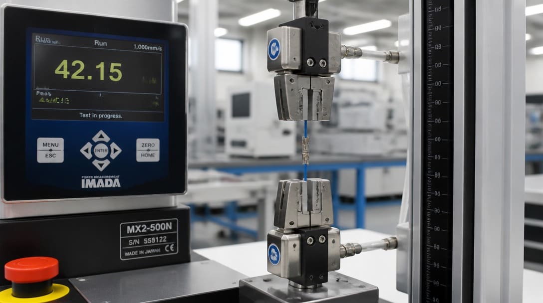
Pull Force Testing and Crimp Height: Why a Crimp Can Pass Continuity but Fail in the Field
A pull force test applies an axial load to the crimped terminal and measures how much force the conductor barrel retains before the stranded copper conductor separates. IPC/WHMA-A-620 provides minimum retention values based on stranded copper conductor size. Crimp height verification with a calibrated micrometer, cross-checked by microsection analysis, confirms that the conductor barrel is compressed within the specified window for the terminal and wire combination.
The typical field return scenario looks like this: the conductor barrel only partially captures the strand bundle, continuity remains green, but vibration and thermal cycles work the terminal loose over weeks or months. The assembly does not fail on the bench; it fails on the machine or in the vehicle. That is why crimp height tolerance and minimum pull force should be defined as mandatory outgoing checks, not optional measurements.
| Wire Size (AWG) | Minimum Pull Force (Class 2 / General) | Minimum Pull Force (Class 3 / High Reliability) | Typical Crimp Height Tolerance |
|---|---|---|---|
| 26 AWG | 13.4 N (3.0 lbs) | 17.8 N (4.0 lbs) | ±0.03 mm (±0.0012 in) |
| 22 AWG | 35.6 N (8.0 lbs) | 44.5 N (10.0 lbs) | ±0.04 mm (±0.0016 in) |
| 18 AWG | 89.0 N (20.0 lbs) | 111.2 N (25.0 lbs) | ±0.05 mm (±0.0020 in) |
| 14 AWG | 222.4 N (50.0 lbs) | 266.9 N (60.0 lbs) | ±0.05 mm (±0.0020 in) |
Hi-Pot Testing: Catching Insulation Breakdown Before It Becomes a Field Incident
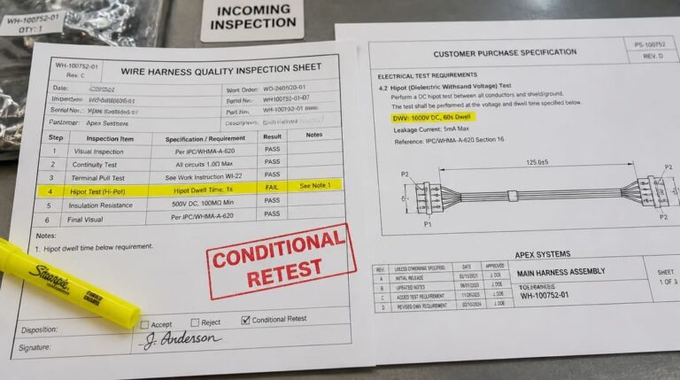
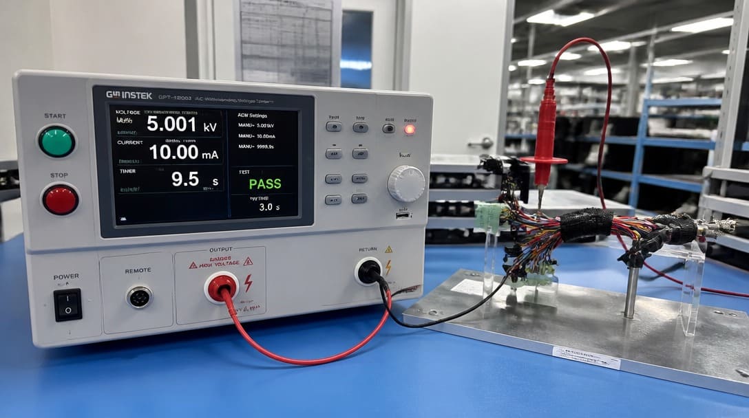
Hi-pot testing applies high voltage between conductors and ground or shield to detect insulation cuts, nicks, pinched insulation support crimps, and creepage failures. A cable can pass continuity but still have a damaged insulation wall that breaks down under operating voltage, humidity, or transient conditions.
Common root causes include stripping damage during wire preparation, incorrect terminal insulation support crimp placement, wrong wire gauge for the terminal, or inadequate clearance between adjacent circuits. Apply hi-pot voltage and dwell time according to product standards or IPC/WHMA-A-620 guidance, and record pass/fail values for traceability. This is the only way to catch insulation breakdown before it becomes a field incident.
Troubleshooting Common Crimp Quality Defects: Causes and Fixes
Follow this sequence when a crimp-related failure appears. The order matters because each test isolates a different failure mode.
| Defect Symptom | Primary Root Cause | Corrective Action |
|---|---|---|
| Low Pull-off Force | Incorrect wire gauge / Worn crimp tooling / Crimp height too high | Recalibrate crimp height; verify wire-to-terminal match per manufacturer spec. |
| Cracked Conductor Barrel | Over-crimping / Crimp height set too low | Increase crimp height slightly; check terminal metal hardness. |
| Strand Breakage / Severed Wires | Incorrect wire stripping / Excessive crimp force | Adjust wire stripper blade depth; verify crimp tooling tolerance. |
| Hi-Pot / Dielectric Failure | Nicked insulation / Misaligned insulation support crimp | Inspect strip length; adjust insulation crimp ears to grip without piercing. |
- Step 1: Confirm the failure mode. Measure crimp height, perform a pull force test, check contact resistance, or cut a sample for microsection analysis. Do not assume continuity failure means a bad crimp.
- Step 2: For low pull force, inspect conductor barrel size versus wire gauge, strip length, stranded copper conductor fill, terminal condition, and crimp tooling wear. Worn tooling is a common cause that external inspection misses.
- Step 3: For over-crimped or cracked terminal barrels, reduce crimp height and verify that the terminal and wire combination meets IPC/WHMA-A-620 acceptance criteria. Over-crimping can break strands and reduce long-term retention despite a tight initial feel.
- Step 4: For hi-pot failure, inspect the insulation support crimp, wire insulation damage, terminal position, and clearance/creepage distances. A pinched insulation support crimp or a nicked insulation wall is often the root cause.
- Step 5: Apply corrective action, re-qualify samples, and document results against IPC/WHMA-A-620 acceptance criteria. Record measured values for pull force, crimp height, and hi-pot pass/fail for traceability.
Building an Acceptance Test Plan That Prevents Field Returns
Set a production-ready test sequence: continuity for routing and open/short detection, crimp height and pull force for mechanical retention, and hi-pot for insulation safety where required. Use microsection analysis during process qualification and when recurring defects appear in production. Sample pull force and crimp height per lot for traceability, and align all acceptance criteria with IPC/WHMA-A-620.
“We made pull force testing and hi-pot standard on every outgoing shipment — not because customers always ask for it, but because the failure modes that cause field returns are exactly the ones continuity testing cannot catch.”
For OEM buyers who require this level of verification(see key factors for OEM buyers), suppliers such as EDOM support requirement review, connector matching, sample coordination, production follow-up, inspection, and export-ready packaging for custom cable assemblies and wire harnesses. The acceptance plan should be defined before tooling release so that every measurement has a pass/fail boundary and every result is traceable back to a lot, operator, and tooling setup.
For the broader harness component context, return to the pillar page on What Is a Wiring Harness? Key Components, Functions & Applications. For final verification, export packaging, and shipment controls, see the separate walkthrough on quality inspection and export packaging. Learn more about wire harness manufacturing services for production-level crimp quality control.
Factory-Level Crimp Quality Checklist for OEM Buyers
- Tooling Verification: Confirm whether OEM-specified applicators or verified equivalent semi-automatic crimpers are used.
- First Article Inspection (FAI): 5-piece crimp height micrometer measurement and destructive pull-force test at the start of every shift/lot.
- Real-time Monitoring: Use Crimp Force Monitors (CFM) on high-speed presses to intercept missing strands or abnormal insulation feed.
- Cross-Section Analysis: Request microsection reports showing zero voiding in the wire core zone for Class 3 projects.
Frequently Asked Questions
Why does a cable assembly pass continuity but fail in the field?
Continuity only confirms an electrical path. A partially crimped conductor barrel, damaged insulation support crimp, or high contact resistance can still complete a circuit in the test fixture. Under vibration, thermal cycling, or humidity, those latent defects develop into open circuits, intermittent shorts, or insulation breakdown.
What is crimp height and why does it matter?
Crimp height is the measured thickness of the compressed conductor barrel after crimping. It indicates whether the terminal and wire combination was compressed within the design window. Too high means low retention force; too low can damage strands or crack the barrel. IPC/WHMA-A-620 requires crimp height verification as part of mechanical acceptance.
Why did my cable assembly fail hi-pot testing?
Common causes include stripping damage that nicked the insulation, an incorrectly placed insulation support crimp that pinched the wire insulation, wrong wire gauge for the terminal, or insufficient clearance between circuits. A hi-pot failure means the insulation wall can no longer withstand the specified operating voltage, even if continuity still passes.
Is pull force testing required for every cable assembly?
Not necessarily for every production unit, but it should be mandatory during process qualification, after tooling changes, and as a per-lot sample during production. IPC/WHMA-A-620 defines minimum retention values by wire size. Buyers should specify pull force as an outgoing check when field failures would be safety-critical or costly to repair.
How does IPC/WHMA-A-620 define crimp acceptance?
IPC/WHMA-A-620 is the acceptance standard for cable and wire harness assemblies. It defines three workmanship classes with increasing inspection and documentation rigor and provides acceptance criteria for crimp height, pull force, insulation support placement, and workmanship. It is the baseline reference for mechanical crimp quality in OEM and export projects.
Key Takeaways
- Continuity testing catches open circuits, shorts, and miswires — but not crimp retention, contact resistance, or insulation breakdown.
- Pull force testing and crimp height measurement are the only practical ways to verify mechanical crimp integrity against IPC/WHMA-A-620.
- Hi-pot testing detects insulation nicks, pinched insulation support crimps, and creepage failures that continuity cannot reveal.
- Microsection analysis should be used during process qualification and troubleshooting to see internal conductor barrel fill, strand damage, and voiding.
- Every acceptance test plan should document measured values for traceability and define mandated outgoing checks before production starts.