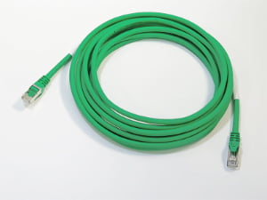
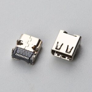
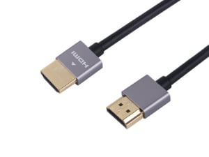
Direct Answer: A rugged robotics cable assembly is a purpose-built interconnect system with environmental sealing, shielded or high-flex conductors, and mechanical strain relief, used to transmit power, signal, or data through robot joints, wet enclosures, and continuous-motion paths without intermittent failure.
The Operating Environment Is the Specification
Rugged robotics cable assemblies fail most often when the operating environment is treated as a packaging detail. Procurement teams may rush to connector pin counts, wire gauge, and cable length before asking whether the assembly will see washdown spray, sub-zero start-up temperatures, or tight bend radii inside a robot arm. By then, performance is already constrained by decisions that are expensive to reverse.
When moisture, temperature, installation space, and motion are defined first, the correct connector family, cable construction, shielding approach, and overmold geometry can be selected in a single pass. When they are skipped, the result is usually not a single obvious failure. It appears as intermittent signal loss, cracked overmolds, failed seals, or broken conductors under repeated flex — problems that require PCB layout and harness routing changes late in the project.
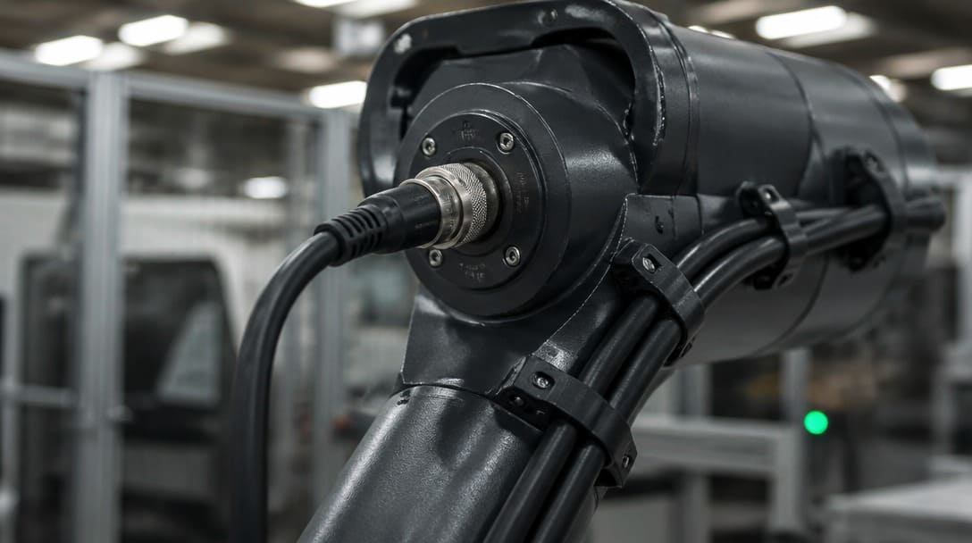
Cable Assembly vs. Wire Harness: Clearing the Most Common Confusion
One of the fastest ways to delay a robotics quote is to call a wire harness a cable assembly. The two are not interchangeable in an RFQ because they imply different protection, testing, and documentation requirements.
A cable assembly groups multiple conductors under a common outer jacket, shield, or overmold. Its purpose is to protect conductors from environmental and mechanical stress, and it is specified at the bundle level. A wire harness routes, bundles, and labels individually jacketed wires with ties, sleeves, looms, or conduit. A harness organizes conductor paths but does not typically seal the entire bundle against moisture or stray EMI.
| Parameter | Cable Assembly | Wire Harness |
|---|---|---|
| Outer protection | Common outer jacket, shield, or overmold | Individually jacketed wires bound with ties, sleeves, or looms |
| Environmental sealing | Designed for sealing against moisture and dust; can include sealed connectors | Generally not a sealed bundle; protection depends on routing and enclosure |
| Overmolding | Common at connector backshells and transitions | Rare; strain relief mostly via grommets or routing |
| Mechanical strain relief | Integrated in overmold or backshell design | Provided by clamps, ties, or grommets |
| Typical robotics use | Joints, wet zones, high-flex paths, sealed interfaces | Inside control cabinets, structural routing, dress packs with external protection |
| RFQ information required | Environment, shielding, overmold envelope, flex rating | Routing length, breakout points, labels, loom or sleeve type |
Mislabeling creates direct RFQ errors. A buyer who asks for a “wire harness” may receive a routed, loom-protected bundle without an outer jacket or overmold sealing — too little protection for a robot joint. A buyer who specifies a “cable assembly” may receive an overmolded, shielded bundle when the real need is simple routing inside a dry control cabinet. The table above is a useful filter: if the requirement includes environmental sealing, overmolding, or common outer protection, treat it as a cable assembly. If the requirement is routing, breakout points, labels, and sleeves, treat it as a wire harness. For production of labeled, loomed, and routed wire harnesses, review the wire harness manufacturing workflow.
Operating Environment Checklist: Moisture, Temperature, Space, and Motion
Before connector selection, four environment factors shape the entire specification.
- Moisture exposure. Define washdown, humidity, condensation, or sealing needs. For wet zones, sealed M12 connectors and M8 connectors rated for IP67 are common. The M12 interface is described by IEC 61076[1]-2-101, which gives buyers a standard reference for dimensions, coding, and environmental sealing. M8 connectors have a smaller body and lower pin count, making them useful for space-constrained sensor and feedback links.
- Temperature range. Specify continuous operating temperature and peak temperature. Jacket and overmold materials must remain flexible at cold start and must not soften or deform during sustained load. This affects material selection for PVC, PUR, TPE, or silicone alternatives.
- Installation space. Map the installed bend radius, connector lock access, and overmold envelope inside the robot arm, cabinet, or sealed enclosure. A cable that fits on a drawing table may not fit when the connector is mated and the lock ring is rotated.
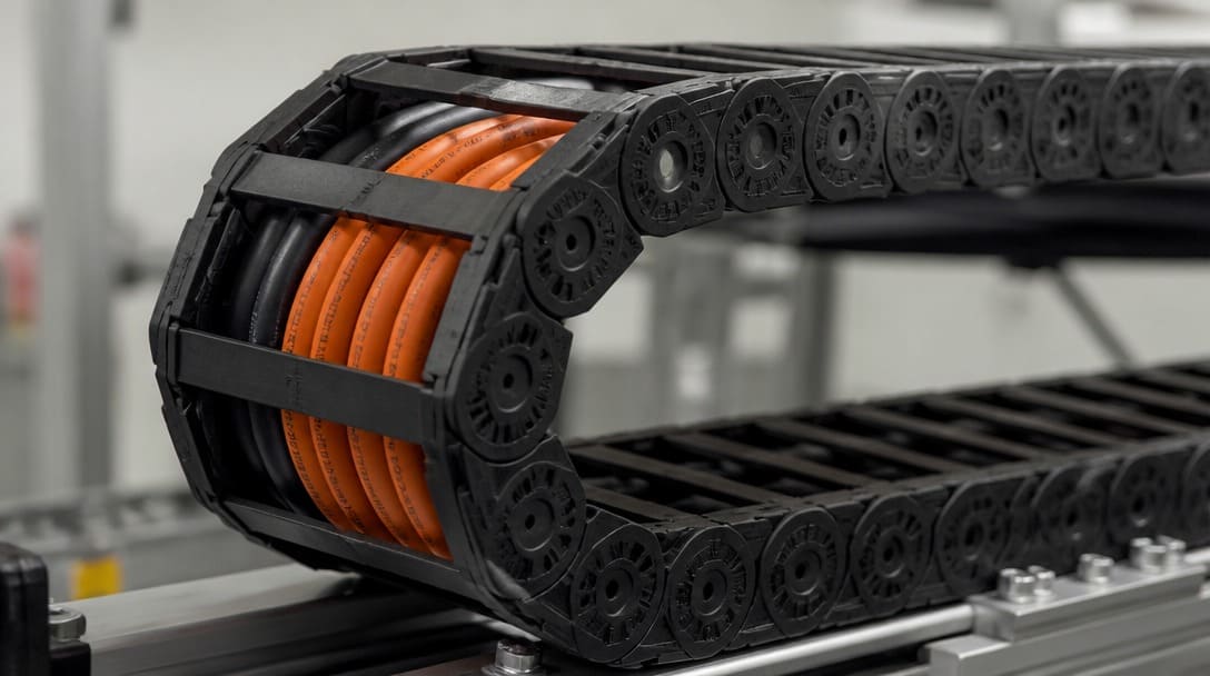
- Vibration or mechanical stress. Choose high-flex cable for continuous bending in articulated joints, drag chain cable for linear motion inside cable carriers, and confirm the torsion rating for rotating joints. High-flex cable uses fine-stranded conductors and optimized lay lengths to withstand repeated flexing; drag chain cable is designed to avoid conductor fatigue in rolling applications; torsion rating defines how much twisting per unit length the cable can tolerate over repeated cycles before conductor or shield damage occurs.
| Environment Factor | What to Define | Specification Impact |
|---|---|---|
| Moisture | Washdown, humidity, sealing requirement | Sealed M12/M8 connectors, IP67, jacket material, overmold adhesion |
| Temperature | Continuous and peak range | Jacket and overmold material, cold flexibility, hot deformation |
| Installation space | Bend radius, lock access, overmold envelope | Cable outer diameter, connector size, overmold height, draft angle |
| Motion or stress | Flex cycles, linear track travel, rotation | High-flex cable, drag chain rating, torsion rating, shielding construction |
Before locking connector types, run the environmental requirements through a cable assembly review that checks connector matching, cable construction, and overmold geometry against the intended installation.
The Overmold Dimension Problem: Internal Layout and Cable Must Be Designed Together
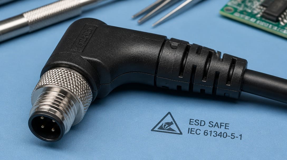
An overmold is not a cosmetic cover. It must fully encapsulate terminations, PCB tails, shield drain wires, solder joints, and strain relief so that moisture cannot reach conductors and no joint is left exposed. If the overmold is too thin, it cracks during flexing or leaves sharp internal components outside the encapsulant. In humid environments, a thin overmold can also create capillary paths for moisture ingress around the cable outer jacket.
The same overmold must also fit inside the mating envelope, enclosure cutout, and assembly channel. If it is too thick, the connector cannot fully seat, the lock ring cannot rotate, or the assembly cannot pass through the cable channel. The result is field assembly problems or a last-minute drawing change.
We regularly see cable assembly inquiries where the drawing shows connector types and wire gauge, but nothing about where the assembly will be installed. When the answer turns out to be inside a sealed enclosure in a humid environment, the entire overmold approach needs to change.
When both constraints are tight, the internal layout cannot be treated as a later step. The PCB tail length, grounding point, drain wire routing, and EMI shielding arrangement must be designed as part of the cable assembly. Otherwise, the board may be too large for the overmold envelope or the shield cannot be grounded cleanly. The broader relationship between operating environment, board layout, and cable construction is part of a specialized cable assembly design framework that covers application-area tradeoffs.
Shielding Selection: Foil, Braid, or Combined
Shielding should be selected only after identifying actual EMI shielding sources in the robot cell. Motor drives, inverters, servo amplifiers, and adjacent power conductors can couple noise into sensor and encoder signals. If none of these are present, adding shield layers only increases diameter, weight, cost, and bending stiffness without solving a real problem.
When shielding is required, the main tradeoff is between coverage and mechanical endurance.
| Shield Type | Coverage Characteristics | Flex Life | Diameter Impact | Cost | Typical Rugged Robotics Use |
|---|---|---|---|---|---|
| Foil only | High optical coverage, continuous conductive layer | Poor; can crack with repeated flexing | Low | Low | Low-motion or fixed segments, inside cabinets |
| Braid only | Lower optical coverage, strong mechanical strength and flex endurance | High | Moderate | Moderate | Robot arms, drag chains, torsional joints |
| Foil + braid | Combines coverage and flex resistance | High | Higher | Higher | Environment with both EMI and continuous motion |
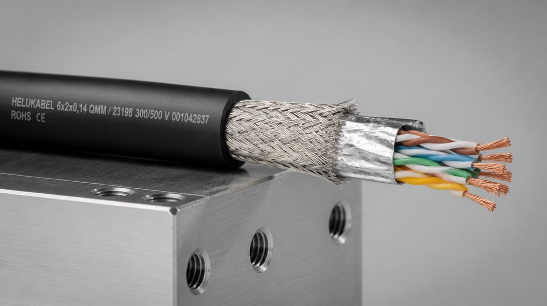
For a robot joint that bends continuously, foil-only shielding is generally a poor choice because the thin conductive layer can crack and lose continuity. Braid provides a flexible, mechanically robust shield with lower optical coverage but better flex life. Foil plus braid offers the highest protection in noisy, high-motion areas but increases cable diameter and bend radius. The specification also needs a clear grounding strategy: a single-ended drain wire termination avoids ground loops but may leave the shield less effective at high frequencies, while both-ended terminations improve shielding but can introduce ground current issues if done incorrectly.
What to Include in a Cable Assembly Drawing to Avoid Redesign Cycles
Most redesign cycles come from missing information on the drawing, not from manufacturing errors. A production-ready drawing should define both the electrical and mechanical boundary conditions in one document.
- Connector calls: M12 or M8 with coding, pin count, mating lock style, and sealing rating such as IP67. For M12 connectors, reference IEC 61076-2-101 for intermateable data and power variants where applicable.
- Wire and cable data: gauge, insulation, color code, pinout table, outer diameter, jacket material, and shielding type.
- Mechanical requirements: bend radius, flex cycles, torsion rating, installed vs free space dimensions, and overmold dimensions.
- Environment notes: moisture, temperature range, chemical exposure, vibration, and expected motion path.
- Acceptance tests: continuity, appearance, IP67 leak test if specified, and flex cycle verification consistent with IPC/WHMA-A-620 acceptance criteria.
A clear drawing allows the supplier to review connector matching, confirm the overmold envelope before sampling, and avoid quoting hidden changes. The same specification discipline applies to the broader class of special interconnects described in the specialized cable assemblies overview.
From Environment Requirements to Production-Ready Assembly
The path from design to shipment follows a sequence: environment checklist, connector and cable and shielding selection, overmold dimension review, drawing and sample confirmation, production follow-up, and export packaging. Each step generates information the next step needs. Skimping on sample confirmation usually moves the failure to final inspection, where it becomes a line-down issue rather than a design correction.
During production, continuity testing and appearance inspection verify the assembly after termination. Final packaging must protect connectors and overmolds from crushing, moisture, and bending during export handling. These steps are covered in the quality inspection and export packaging workflow.
Suppliers such as EDOM Electronics support OEM buyers with requirement review, connector matching, sample coordination, production follow-up, inspection, and export-ready packaging for custom cable assemblies and wire harnesses.
For a broader overview of specialized cable assemblies across application areas, revisit the specialized cable assembly design guide.
Frequently Asked Questions
What is the difference between a cable assembly and a wire harness in robotics?
A cable assembly uses a common outer jacket, shield, or overmold to protect conductors from moisture, EMI, and mechanical stress. A wire harness bundles individually jacketed wires with ties, sleeves, or looms for routing and identification, but does not typically seal the entire bundle. Robotics projects use both: cable assemblies for joints and sealed interfaces, harnesses for cabinet routing and structural paths.
When should a robotics cable assembly be shielded?
Shielding should be specified when motor drives, inverters, servo amplifiers, or adjacent power conductors can couple noise into sensor, encoder, or communication lines. Foil provides high coverage but poor flex life; braid handles motion better; foil plus braid balances coverage and endurance. The grounding strategy for the drain wire must be defined in the drawing.
What does IP67 mean for robotics connectors?
IP67 means the connector is protected against dust ingress and temporary immersion in water. In robotics, IP67-rated M12 and M8 connectors are common for washdown zones and humid environments. The mating performance of M12 circular connectors is standardized by IEC 61076-2-101, giving buyers a reference for intermateability and sealing.
How much space should be reserved for an overmolded connector?
Space should be defined from the actual mating connector and enclosure layout, including lock ring rotation, cable bend radius, and shaft clearance. The overmold must be thick enough to encapsulate terminations and strain relief but thin enough to fit inside the available channel and mating envelope. Tight installations require the PCB tail and shield drain routing to be developed with the cable assembly, not after it.
How should OEM buyers evaluate a cable assembly supplier?
Look for a supplier that reviews drawings before quoting, confirms connector matching, provides samples, and follows through with production tracking, continuity testing, appearance inspection, and export packaging. EDOM Electronics supplies OEM buyers with this sequence for custom cable assemblies and wire harnesses. Avoid suppliers that quote only on wire gauge and length without asking about installation environment or overmold envelope.
Key Takeaways
- Operating environment must be defined before connector or cable selection; moisture, temperature, space, and motion drive the specification.
- A cable assembly provides environmental and mechanical protection under a common jacket, shield, or overmold; a wire harness routes and labels individually jacketed wires.
- Overmold dimensions create a hard tradeoff between encapsulating internal terminations and fitting the installation envelope; tight cases require PCB, grounding, and shielding design as part of the cable assembly.
- Shielding should be selected as foil, braid, or combined based on EMI sources and flex life, not as a default.
- A complete drawing with connector calls, cable data, mechanical requirements, environment notes, and acceptance tests reduces quote and sample loops.
Explore custom cable assembly solutions for requirement review, sample coordination, and production-ready builds.